Be72 DIESEL ENGINE KEY START MODULE
BE72 INSTALLALATION MANUAL
SUITABLE FOR DIESEL ENGINE-DRIVEN EQUIPMENT
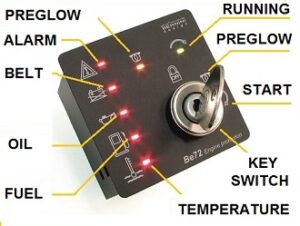
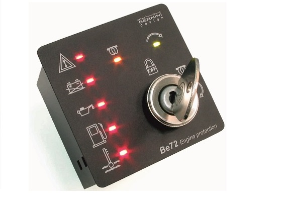
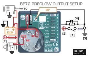
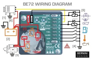
The BE72 diesel engine KEY START module includes the essential safeguards to protect a diesel engine. It features 7 LEDs, 3 Static Outputs, and a 30A Key Switch. It monitors an Oil Pressure-switch, Temperature-switch, Fuel Level-switch, Charger Alternator Voltage, and an Emergency-switch. The BE72 provides a MANUAL operation via a 30A Key- switch. Adjustable settings include pre glow timing and stop solenoid timing. The fully coated controller is fitted on a rugged rust-proof metallic enclosure with a standard DIN72 cut-out.
BE72 KEY FEATURES
> 30A dc Key-switch for manual start
> Short-circuit-proof solid-state outputs
> Din size 72, 40mm depth, shock-proof
> Full 3-year warranty, cost-effective
> -30°C up to +70°C operating temperature
> 5,5 to 36Vdc operating voltage range
STEUERUNG FÜR MANUELLEN AGGREGATSTART BE72
The Be72 provides a Manual start for engine-driven applications. Automatic fault protections include Engine low oil pressure, High Temperature, Emergency, and Belt break. The Be72 provides the following outputs: Start, Stop, Preheat, Alarm, and Fuel solenoid. Be72 features a power switch (30A current) to energize the starter. All functions are indicated by means of 7 LED indicators.
MANUAL DE USUARIO CONTROLADOR Be72
PURCHASE
ONE SAMPLE
119.00€/each
PURCHASE TWO PIECES
99.00€/each
YOU CAN PAY VIA BANK TT BY ASKING FOR A PROFORMA INVOICE TO
[email protected]
PURCHASE FOUR PIECES
64.00€/each
BE72 KEY START OVERVIEW