ATS CONTROLLER WIRING DIAGRAM
FOLLOW OUR ATS CONTROLLER WIRING DIAGRAM TO MAKE COST-EFFECTIVE ATS PANELS

ATS CONTROLLER WIRING DIAGRAM PDF
Get the most from an automatic transfer switch! Follow our recommended ATS controller wiring diagram. The big picture is a backup system that includes a power generator. The logic is grounded on a solid rock ATS controller BeK3. You will install the transfer switch and the ATS controller in a suitable metal cabinet. The result will be an easy-to-connect and cost-effective ATS panel. You can connect the ATS panel to diverse generators, including the refurbished ones. In this ATS controller wiring diagram, you will see how the ATS controller automatically governs all functions by managing the connection assignment of the LOAD to MAINS or GENERATOR. There are two options for connecting the LOAD to MAINS or GENERATOR: via contactors and motorized transfer switches.
THE TWO BASIC ATS CONTROLLER WIRING DIAGRAMS
Even though the final goal is to build a backup power system, there are two basic configurations: CONTACTORS-CHANGEOVER and MOTORISED-CHANGEOVER, These are based on the technology used to transfer the LOAD from MAINS to GENERATOR and vice versa. Let us see an overview before diving into the schematics wiring diagram. The ATS controller governs the system and transfers the load to the GENERATOR or MAINS smoothly and with short downtime. A delay time between the switching it is mandatory. Advanced ATS controllers like BeK3 and Be242 feature an adjustable delay time. It will avoid dangerous sparks on the contactors or transfer switches. The ATS controller adds a delay before activating a LOAD. A fast switching form GENERATOR to LOAD, for example, could be dangerous in case of inductive loads. In general, the ATS connect the LOAD only if the primary (call it MAINS) and secondary sources (call it GENERATOR) are stable within appropriate settings,
CONTACTORS-BASED SOLUTION
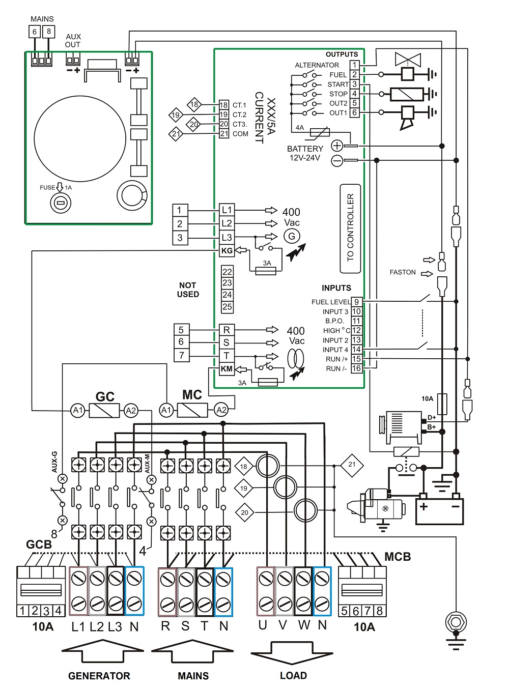
A transfer switch made with contactors requires 2 contactors of suitable size. The two devices are mechanically interlocked. In other words, it is not possible to energize both. An electrical interlock is also added using auxiliary contacts. We can say that there are two levels of protection. This prevents backfeeding. Concerning the WIRING DIAGRAM 1, the terminals involved in the control of the contactors are (KG), (KM), (PHASE L3), (PHASE T), (4), and (8).
The MAINS to LOAD connection
The four-pole MC contactor connects the LOAD to MAINS. The MC coil energizes via the output (KM) and auxiliary contacts (AUX-G). The COIL of the MC is supplied via terminal (4) on one side and phase (T) of the MAINS via the (KM) terminal. When the utility power fails, the ATS controller deactivates the output (KM); the MC consequently disconnects the LOAD. Once the MC is open, the auxiliary contacts (AUX-M) close to pre-enables the GC contactor. The following picture visually shows the connections of the auxiliary contacts. In the pictures, the symbols (A1) and (A2) indicate the connection points for the coils of the contactors.
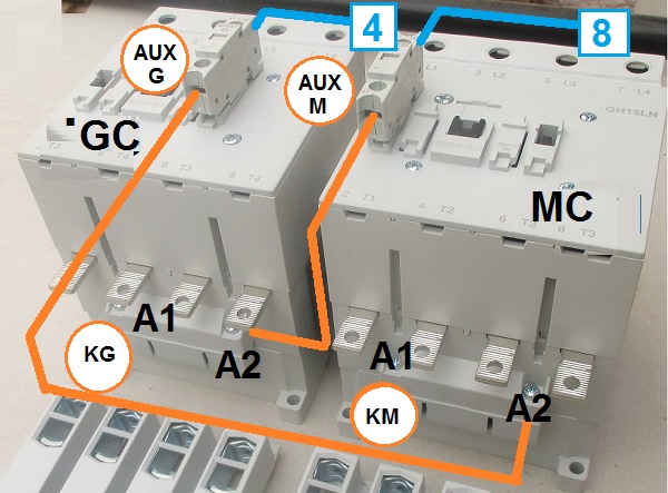
The MAINS to GENERATOR connection
When the ATS controller activates the output (KG), the GC will energize to transfer the LOAD to the generator. This is possible because the MC contactor is in its open status. The contacts (AUX-M) on the body of the MC contactor are closed. The GC can energize only when the KM is in its open status. The Neutral terminal (8), and phase (L3), wires of the generator supply the coil of the KG. When switching the generator to MAINS, the user observes a short ‘power outage’. This is normally 2 seconds. This is the typical behaviour of the automatic transfer switch based on contactors: BREAK-BEFORE-MAKE.
WIRING DIAGRAM Nr.1
ATS CONTROLLER WIRING DIAGRAM LEGEND
GCB Generator circuit breaker, usually 10 amps. It protects the internal auxiliary circuit inside the panel.
MCB Mains circuit breaker, usually 10 amps. It protects the internal auxiliary circuit inside the panel.
AUX-G Auxiliary contacts installed on the body of the GENERATOR CONTACTOR
AUX-M Auxiliary contacts installed on the body of the MAINS CONTACTOR
GC GENERATOR CONTACTOR, normally in the range of 63 up to 150 amps
MC MAINS CONTACTOR, normally in the range of 63 up to 150 amps
KM Terminal of the interface board committed to energize the MAINS CONTACTOR
KG Terminal of the interface board committed to energising the GENERATOR CONTACTOR
MOTORIZED TRANSFER SWITCH-BASED SOLUTION
AUTOMATIC TRANSFER SWITCH: MAINS-LOAD
The motorized changeover consists of a motorized switch with 3 positions: GENERATOR, OFF and MAINS. An electric motor drives the switch to move in a particular position. The motorized changeover has several advantages. Firstly, it can manage big currents if compared with a contactor-changeover. Secondly, it does not require power to hold the position. Thirdly, it is a cheap and safe solution for high-power switching. On the other hand, the system is not so granular when you need flexibility of operation.
WIRING DIAGRAM Nr.2
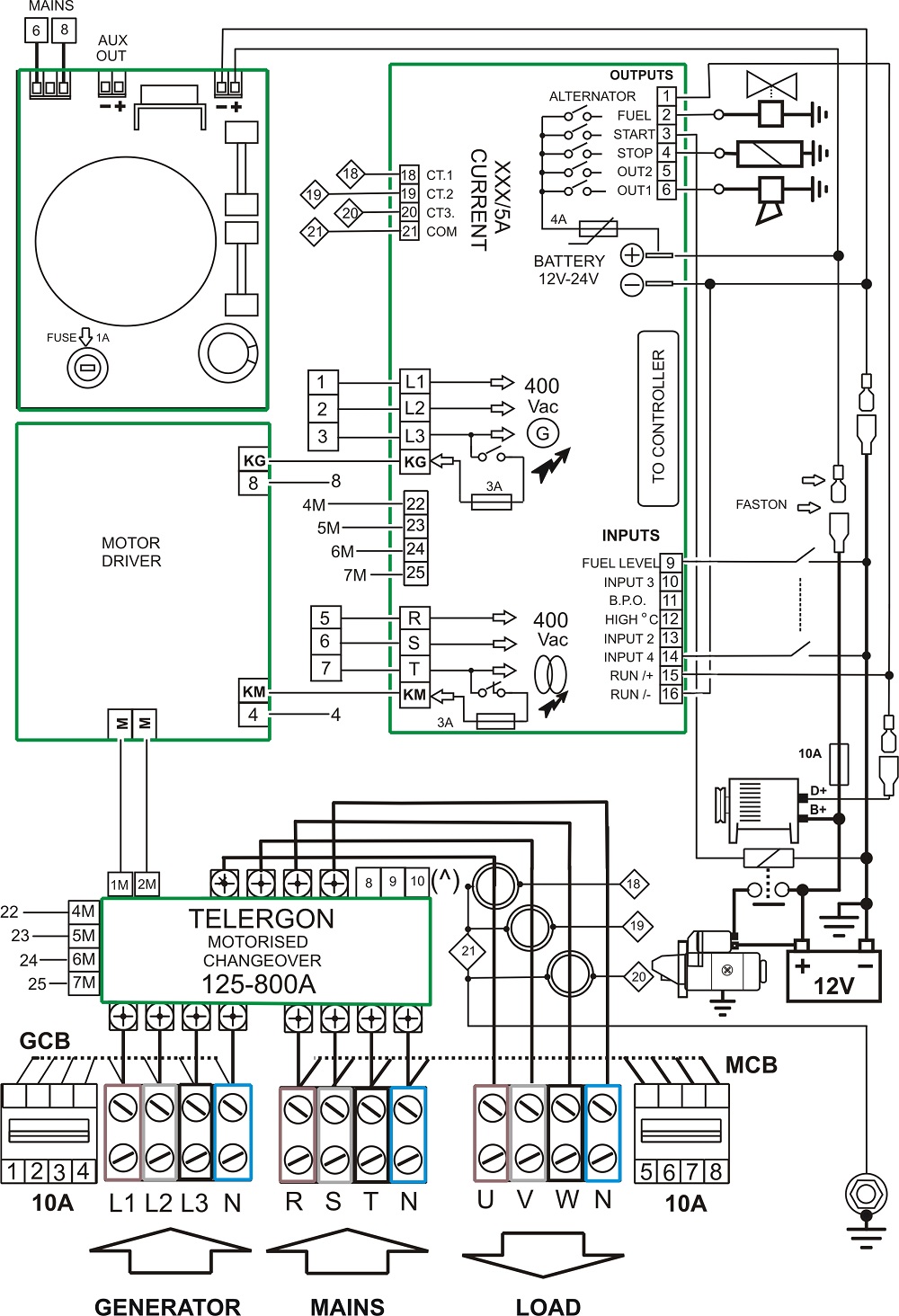
The interface board connects the changeover with 4 wires. The board sends electric pulses for about 200ms to instruct the changeover. The MOTOR DRIVER board supplies the electric motor only when necessary.
ATS CONTROLLER ADDITIONAL CONNECTIONS
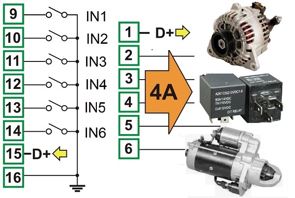
The additional connections consist of all wires necessary to interface with the generator. In particular start and stop commands for the engine. The universal ATS interface board does include protection fuses. In general, you have to connect the following items.
ENGINE INPUT-OUTPUT TERMINALS
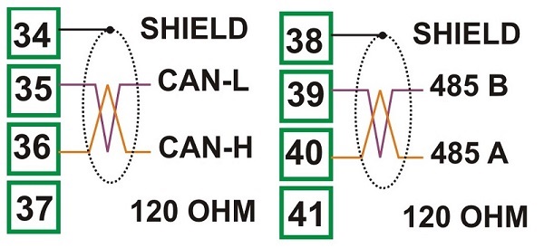
CANbus and MODbus CONNECTIONS
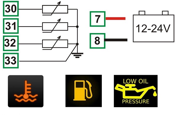
ENGINE SENSOR CONNECTIONS
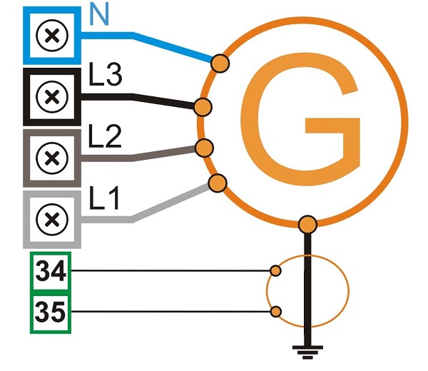
ALTERNATOR CONNECTION
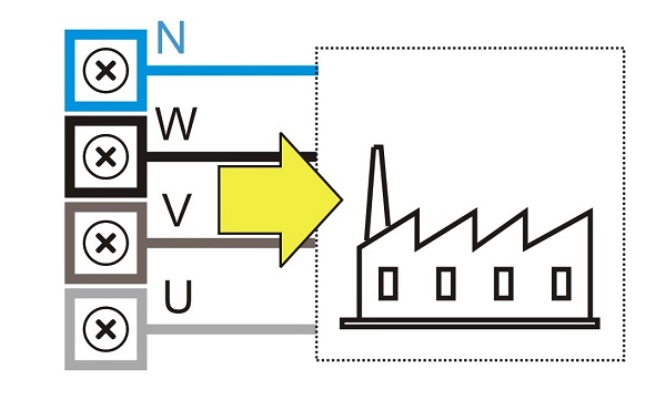
LOAD CONNECTION
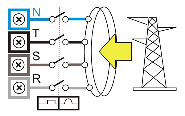
UTILITY POWER CONNECTION
READ MORE ABOUT ATS CONTROLLERS AND HOW TO MAKE COST-EFFECTIVE ATS PANELS
BERNINI DESIGN SRL
ITALY Industrial Park
46035 OSTIGLIA
SUPPORT
+39 335 70 77 148