ATS Controller: The Smartest Guardian of Your Standby Generator.
The ATS controller manages all functions of an ATS (Automatic Transfer Switch) panel. It controls the flow of power between a "Primary Source" (the mains) and a "Secondary Source" (a Diesel Generator for example). Imagine the ATS panel as a junction with two inputs and a single output: the ATS controller constantly monitors the incoming sources for the output perfect performance.
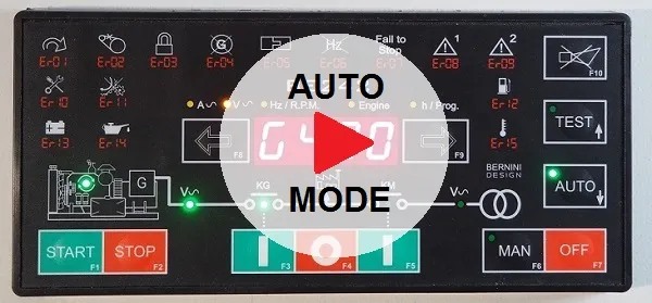
The ATS controller task is simple but crucial:
COMPARE and ANALYZE: dozens of electrical parameters and digital inputs in real time.
DECIDE and CONNECT: the output to the source that provides the best parameters. If both are valid, it always favors the "Primary" source. It drives digital outputs to perform special tasks.
REACTS: In the event of the absence or failure of the primary source, it automatically activates alarms or turns on the emergency generator to avoid power outages.
By installing the Be242 ATS controller, you eliminate the need for external components or complex wiring for driving contactors or motorized switches.
The Be242 features fully adjustable settings for any emergency standby power application.
Build your ATS panels in the shortest time!
A traditional ATS controller needs as many meters of cables, as many connections and as many accessories.
Traditional ATS controllers often require extensive cabling, complex connections, and numerous accessories. The Be242 controller changes this, featuring a simplified, two-part design.
 By installing the interface relay board directly on the backplane, you streamline the connection of engine auxiliary circuits, drastically reducing assembly time. You will benefit from the following features:
-Unmatched Efficiency: Reduce ATS panel assembly time by 50% and save up to 20 meters of wiring.
-Space & Component Optimization: Eliminate the need for up to 5 traditional auxiliary relays; the design requires only a single round hole for mounting.
-Universal Compatibility: Acts as a drop-in replacement for any AMF controller and interfaces seamlessly with both modern and legacy generator sets.
-Robust Engineering: Designed for 30+ years of continuous service, with the CPU unit shielded securely behind the panel door.
-Flexible Control: Features over 60 adjustable settings to handle any application, easily driving both contactors and motorized switches.
-Reliability-First Design: We have prioritized physical durability and simplicity—no fragile LCD displays, just a straightforward, user-friendly interface.
Build You ATS Panel Today!
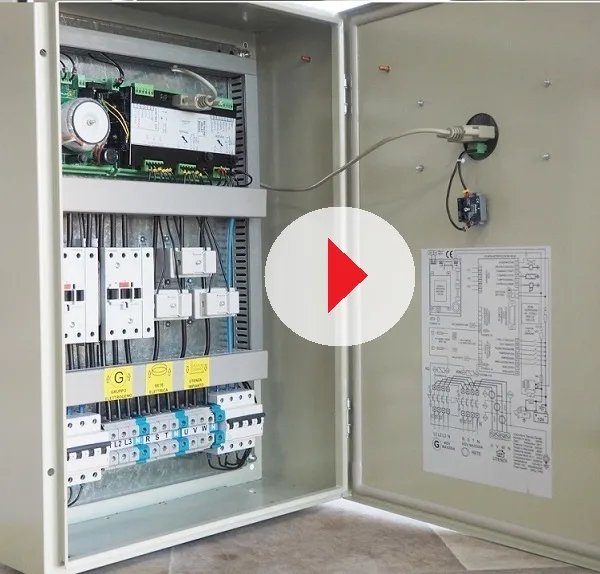
HOW TO BUILD ATS PANELS IN A SHORT TIME
ATS Controller Wiring Diagram Tutorial.
For long-term reliability and electrical safety, the wiring of the Be242 is divided into two distinct layers: AC and DC.
Isolated Architecture: Connections on the interface relay board are strictly separated via high-quality, removable connectors, ensuring clean signal paths and preventing interference.
AC Layer: Dedicated terminals reserved exclusively for Mains and Generator power inputs.
DC Layer: Standardized connections for automatic engine start/stop functionality, plus additional general-purpose Input/Output (I/O) terminals for auxiliary automation.
For complete implementation details, please refer to our comprehensive installation guide:
ATS Controller Price: Our Offer.
The price of this ATS controller will surprise you. It is the only ATS controller with a universal relay interface board. Ask for an OEM quotation. If you are a panel manufacturer, ask for an offer. We can offer an extraordinary discount for 10-25, or a 50-piece bulk order. You can also purchase a sample online directly from us.
We offer free shipping benefits worldwide.
ATS Controller Basic Specifications
BE242 INSTLLATIOIN MANUAL
DC Supply: 5.5/30Vdc, 50/150mA
Dimensions: 194 X 146 X 205
Panel Cut-out: Round 60mm
Operating temperature: -30 to +70 deg C
Weight: 300 grams
LED Indicators for all functions
Over 60 programmable adjustable settings
Interface board dimensions: 210 X 150 X 80 (mm)
Installation: DIN-RAIL
DC Relay Outputs: 3A 30VDC.
AC Relay Outputs: 8Amp 250V AC
Operating Vac: up to 600Vac
Overvoltage Voltage: 2KVac
CTs: up to 1000/5Aac
BERNINI DESIGN SRL
ITALY Industrial Park
46035 OSTIGLIA
BERNINI@BERNINI-DESIGN.COM
SUPPORT
+39 335 70 77 148