AMF Controller Tutorial
The AMF controller governs all functions of a standby generator. It automatically manages the connection assignment of the LOAD to MAINS or GENERATOR. In other words, it is an intelligent form of automatic mains failure relay. AMF is a term of British origin intended to define a set of relays and timers capable of detecting an anomaly on the mains. The introduction of microcontrollers in the 1980s enabled the manufacture of compact electronic modules that offered an all-in-one solution. Typical examples of AMF controllers from the past are the AMT910 and Be21 AMF controllers. The proper destination of an AMF controller is inside the AMF panels. An AMF controller shares some similarities with an ATS controller, which is the core of an ATS panel. This subject is a source of several technical controversies. To find out more, you can visit the page
AMF Controller Price
EAN0793596902871
Free Shipping 5-year Warranty
ONE SAMPLE
299 €
TWO PIECES
2 x 249=498 €
FOUR PIECES
4 x 199=796 €
Support WA +40721241361
Ask a quote for a 10, 25, 50 or 100 pieces bulk order to bernini@bernini-design.com
BeK3 Universal AMF Generator Controller
The BeK3 universal AMF controller is the definitive solution for replacing any type of generator emergency control unit. Whether you are building new generator sets or refurbishing existing equipment, the BeK3 AMF controller offers a competitive price and a wide array of features designed to add significant value to your product.
The AMF controller compares the electrical parameters of the MAINS (that is, the Utility Power) with a set of internal settings. When one or more parameters are out of range, the relay triggers the Mains Failure Flag. This could be used to perform miscellaneous functions: disconnect the load and start the engine for example. The AMF controller is designed for general-purpose standby applications.
Click Full Size Image
 Learn How To Build Standby Generator Control Panels
100m Range Bluetooth AMF Control Monitoring
Use your mobile to get hundreds of information about the status of your standby generator. The BeK3 features the latest Microchip RN4020.

By using our app, you can set a default page on your mobile. Forget tedious and boring data browsing of the AMF front panel. Open your app to get an immediate overview of the system. Get immediate notifications about alarms as well.
AMF Controller Topics List
HOW DOES THE AMF CONTROLLER WORK?
The AMF controller features a 128X64 graphic display, operating in a temperature range between -15°C and +50°C. It indicates parameters, alarms, and miscellaneous information about your standby generator's status. The measurements include Vac, Aac, Vdc, kVA, kVar, kW, Energy, Pdf, Hz, hour count, R.p.m., Oil Pressure, Engine Temperature, Battery Vdc (Engine), Fuel Level and a variety of miscellaneous data and parameters. At the same time, the AMF controller complies with NFPA-110 / NFPA-99 specifications.
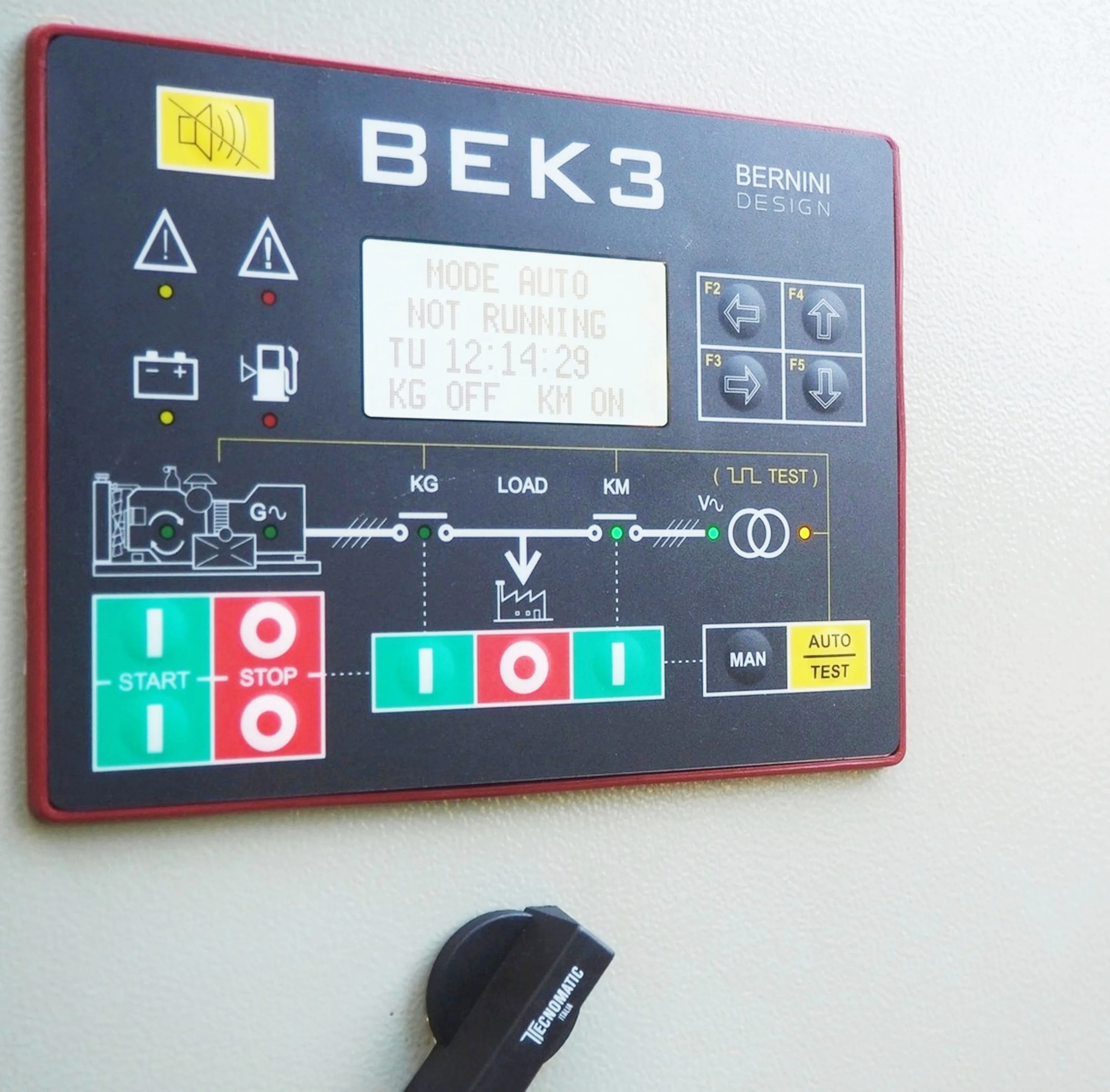
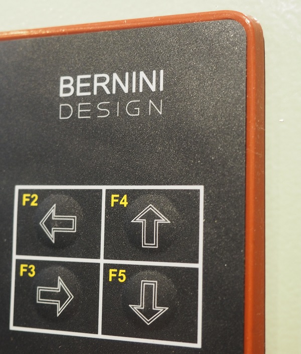
THE FRONT VIEW
The AMF controller is usually placed on the front door of the AMF control panel. A user-friendly interface made of push buttons and LED indicators offers instantaneous information about the status of the entire standby system.
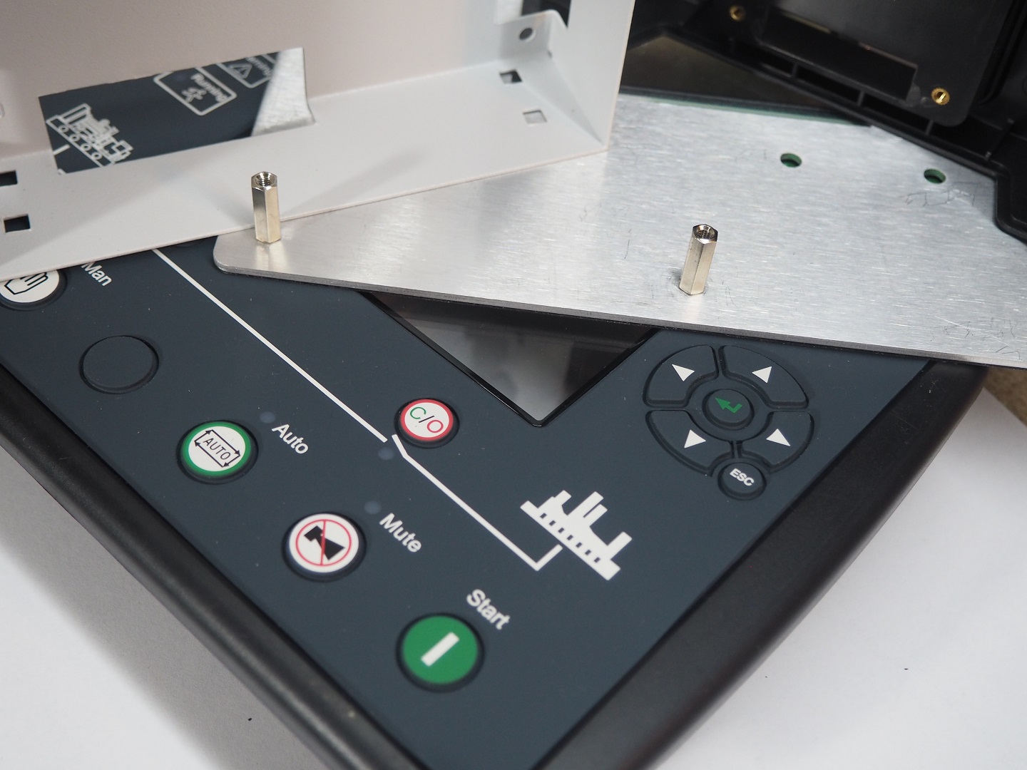
A GOOD AMF CONTROLLER DESIGN STARTS WITH THE ENCLOSURE
What are the differences between a Bernini Design AMF controller and the "PRODUCTS" of the market? We do not mention the totally different implementation of Bernini Design software, nor do we mention the functional safety described by IEC61508 as well. It may require 20 web pages. But, by holding in your hand a Bernini Design BeK3 AMF controller, you will feel the
compactness and the robust design. Not to mention that we use metals like copper, aluminium, and steel. The front panel features a 2mm thick ALUMINIUM-ALLOY shield. The rear cover is made of magnetic iron alloy.
CLICK THE IMAGE TO OPEN HD
These metals reflect and absorb electromagnetic waves, preventing noise penetration or emission. We serve customers who install an AMF controller and forget about it for decades.
SILICON GASKET UV-PROOF
The BeK3 AMF controller, thanks to a silicon gasket, is IP65-compliant.
 This prevents humidity and dust from deteriorating the inside components of the panel.
A "ROCK SOLID " AMF CONTROLLER WITH AN ENCLOSURE MADE OF "STEEL"
A reliable AMF controller features a metallic rear cover. It is about an iron-based alloy suitable to shield magnetic fields. The enclosure is made of zinc double-coated steel. Zinc is a heavy element, and when alloyed with other metals, it provides better corrosion resistance, stability, dimensional strength and impact strength.
THE REAR VIEW
 The rear cover, made of metal, is the best solution for shock-proof equipment. It is an excellent protection against electromagnetic fields by enclosing the 32-bit processor in a Faraday cage. An AMF controller with a metallic enclosure provides an extraordinary advantage over competitors' plastic-based enclosures.
FIGHTING WITH OVERVOLTAGES
Bernini Design has understood the importance of overvoltage protection since 1984. There is a comparison picture of a "MARKET" AMF controller and a BERNINI DESIGN AMF controller. A common manufacturer uses 2 resistors with a few hundred V ratings. Bernini Design has 6 resistors in the chain.
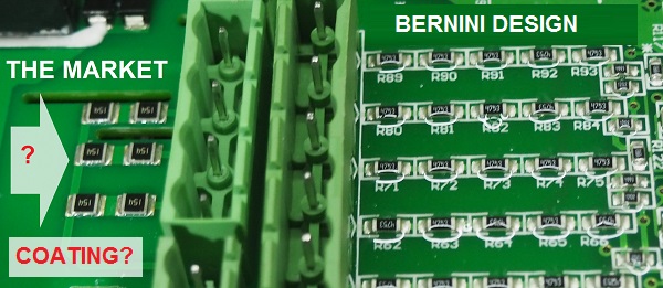
Bernini Design AMF controller features 6 resistors for each phase, in conjunction with a 250 micron layer of conformal coating, the AMF controller can withstand peak overvoltages of about 5kV.
AMF CONTROLLER REMOVABLE CONNECTIONS
The AMF controller features a set of removable connectors organised in order. Using different connectors avoids unpleasant mistakes. Connecting a connector one by one allows for easy AMF controller troubleshooting.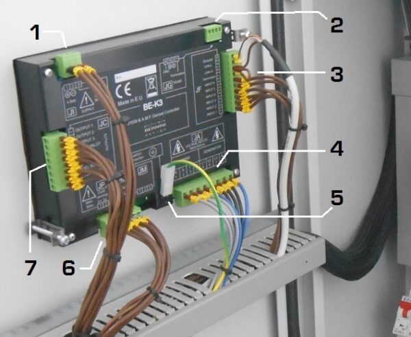
In the above picture, you can observe the following connections:
[1] Power supply [2] Modbus port [3] Digital / Analogue Inputs / CanBus [4] Generator & Utility power connections [5] Protection Ground [6] Current transformers
CANBUS AND MODBUS
Regarding engines with ECU, this AMF controller features a fully isolated CANbus. It supports the J1939 protocol.
CANBUS terminals are also provided on this connector (your ECU must be SAE J1939 compliant).
MODBUS-RTU
The AMF controller features an powerful RS-485 serial interface, it can drive a 1000m twisted pair and 127 nodes. It completely supports the MODBUS-RTU protocol.
AMF CONTROLLER MODBUS PROTOCOL
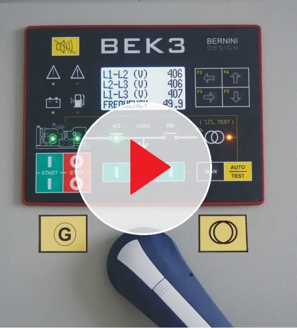
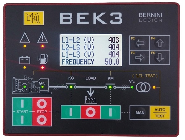
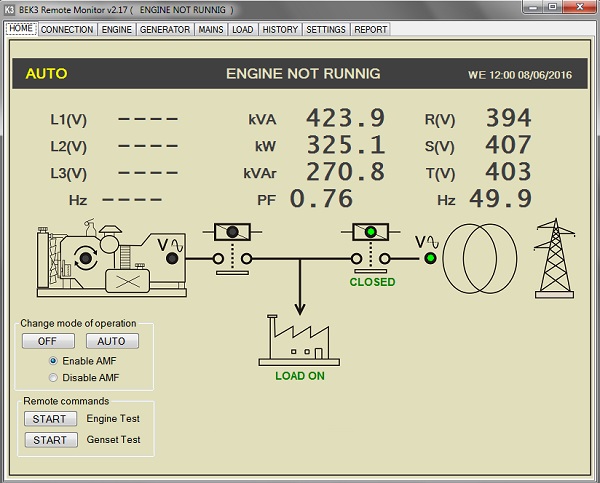
We supply accessories and serial interface adapters with free-of-charge remote monitoring software. In the following example, the Mains is connected to the generator. The screen displays all electrical parameters.
In this example, the LOAD is connected to the GENERATOR. The screen displays all electrical measurements.
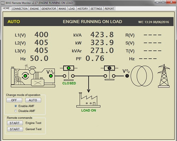
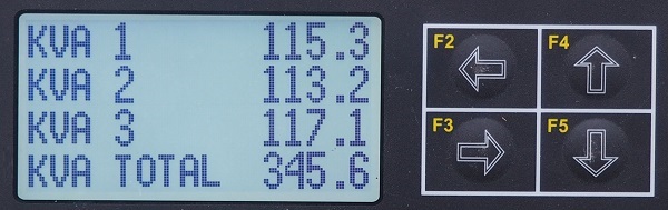
The AMF controller display offers an extraordinary measurement overview of the AMF system with navigation buttons that provide a user-friendly interface. All menus are divided into logical groups: GENERATOR, MAINS, ENGINE, POWER, etc.
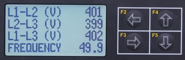
In this example, the AMF CONTROLLER GENERATOR VOLTAGE MEASUREMENTS
 In this example: the AMF CONTROLLER KVA MEASUREMENTS
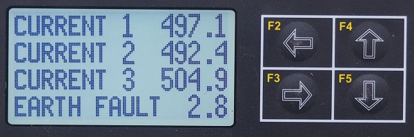
In this example: AMF CONTROLLER CURRENT MEASUREMENTS
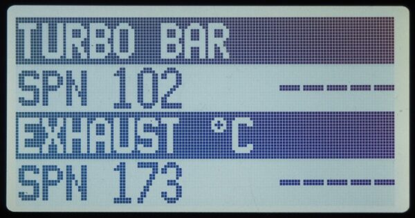
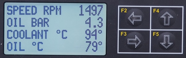
In this example, the AMF CONTROLLER ENGINE CRITICAL PARAMETER
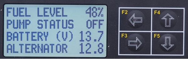
In this example: the AMF CONTROLLER ENGINE MISCELLANEOUS PARAMETER
The list of all display screens is described in the installation manual. This will include informative pages used in troubleshooting.
EARTH FAULT MONITORING
This advanced, state-of-the-art AMF controller features current earth fault via a C.T.. You can set up a shutdown limit.
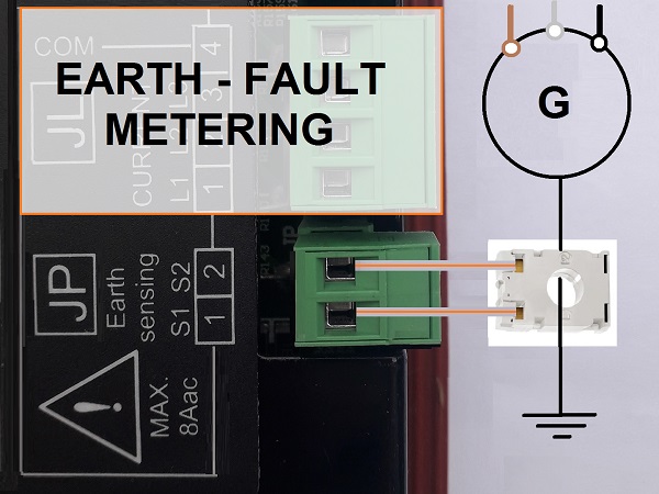
You must connect a current transformer of a suitable size and then program the full scale of the C.T. accordingly.
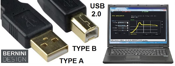
Despite the possibility of setting up the controller by using the navigation buttons and display, the BeK3 controller offers a USB 2.0 connection. You can plug a B-TYPE male connector on the Be-K3 and an A-TYPE male connector on your computer. The software is provided free of charge.
PANEL MANUFACTURER SETTINGS
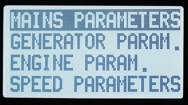
When the AMF controller is placed in the OFF mode, the display shows the MAIN MENU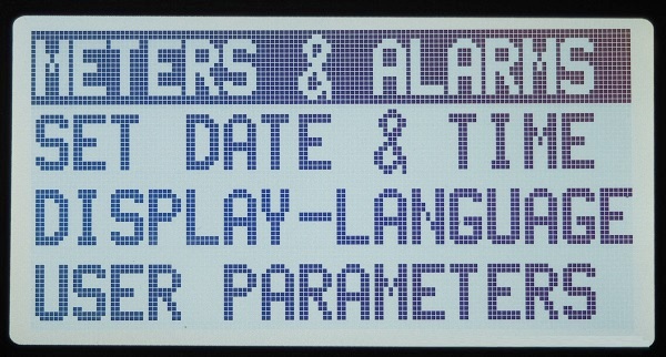
It consists of two pages that include all programmable and adjustable settings. USER and OEM parameters include all settings required for an efficient STANDBY SYSTEM. Some important parameters have a factory setup. Other parameters are inhibited by default.
By choosing the METER & ALARM menu, a list of all instruments appears on the screen.
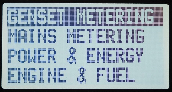
The display shows instruments about GENERATOR, MAINS, FUEL, and others.
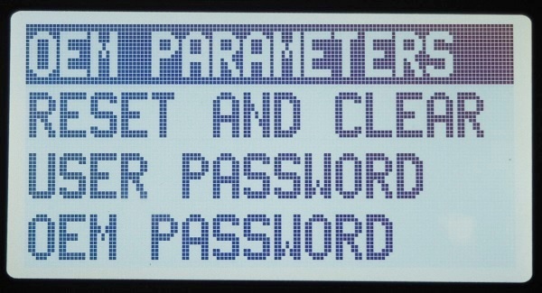
THE OEM PARAMETERS
OEM parameters are included in three menus, the first one includes the most important parameters.
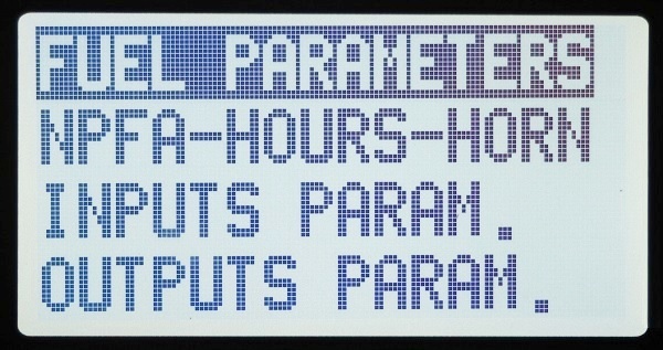
The second page presents miscellaneous options that include INPUT-OUTPUT programming.
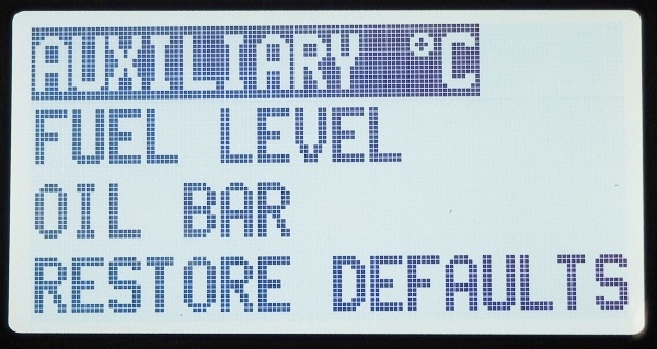
With the last one, you set up an auxiliary temperature channel, Fuel Level and OIL pressure. You can also restore the factory settings.
END-USER SETTINGS
This menu is reserved for the end user. There are wide choices for scheduling the service (oil change, for example).
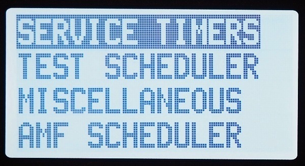
The user can disable the AMF controller during the weekend. He can set up periodic tests for the engine and miscellaneous settings related to the optimal use of the standby generator.
AMF Controller Wiring Diagram
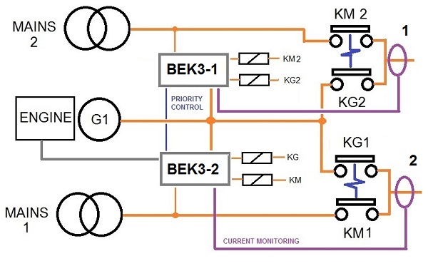
This AMF controller application wiring diagram shows the basic connections.
In particular, this example shows how to make a CONTACTORS-BASED AMF panel. The version capable of driving motorised transfer switches is more complex. It is explained in the MOTORISED-SWITCH section.
Click Full Image Size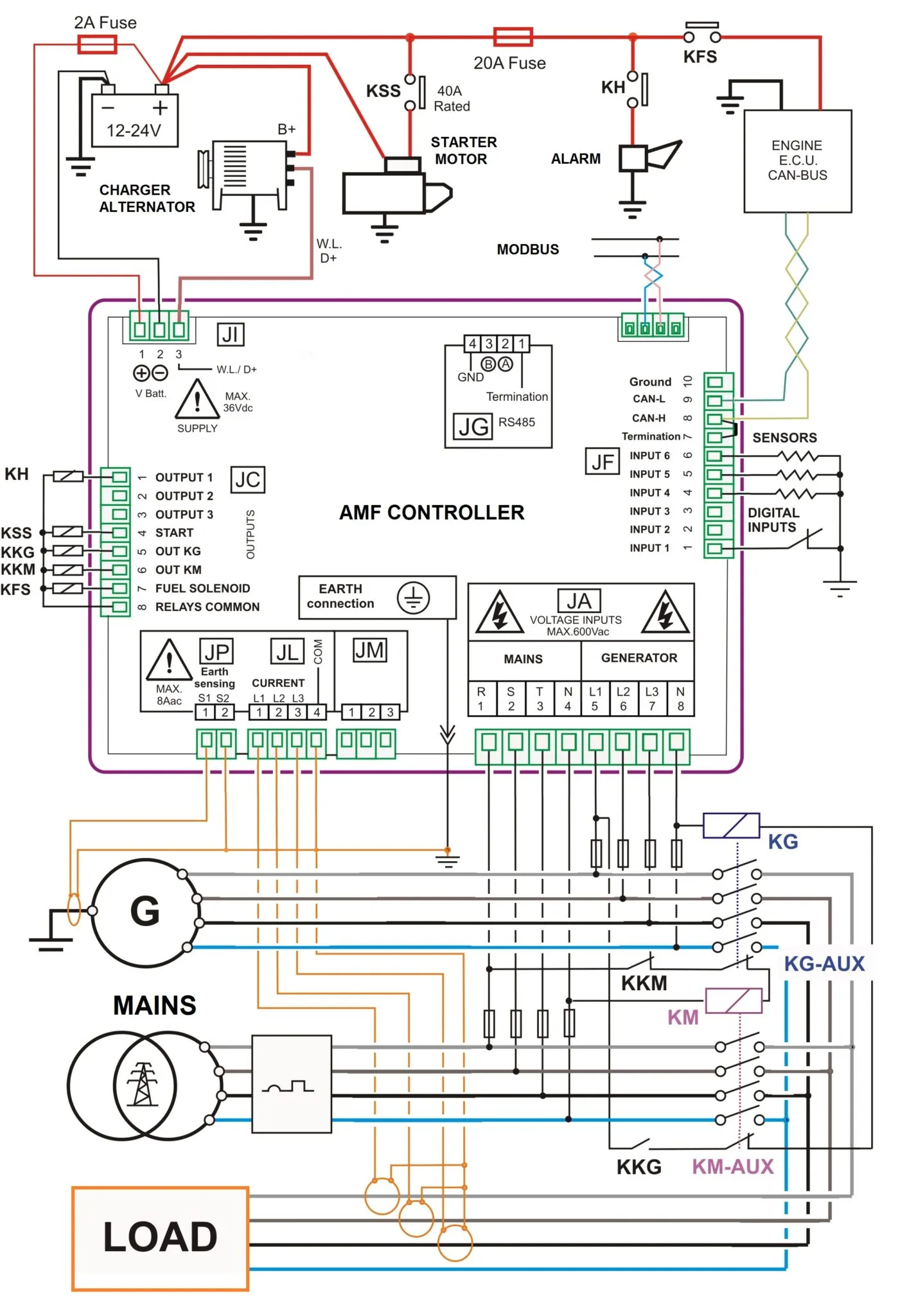
The AMF wiring diagram shows digital and analogue inputs committed to interfacing the engine. You can see the MAINS and GENERATOR connections, CURRENT TRANSFORMERS connections and various mandatory connections. The next sections describe all the details.
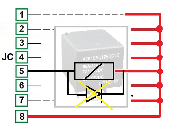
On the removable connector JC, you are required to wire auxiliary relays. The AMF controller provides a common supply rail (JC8) suitable for automotive relays, providing at the same time over-voltage protection, short circuit protection, and EMI protection. You are required to use 90-200 OHM DC coil relays (12 V or 24, according to your engine battery).
Flywheel diodes are included in the controller.
The AMF controller's outputs are described in the following table:
| #JC-1 | Configurable Output 1: You have 80 settings for this output. In other words, 80 different automation functions. |
| #JC-2 | Configurable Output 2: You have 80 settings for this output. In other words, 80 different automation functions. |
| #JC-3 | Configurable Output 3: You have 80 settings for this output. In other words, 80 different automation functions. |
| #JC-4 | Start Pilot output. Connect the terminal "50" of the starter motor via a pilot relay. The minimum recommended rating is 50 amps. |
| #JC-5 | Contactor Generator output. You can connect the driver relay KKG for the GCB (GENERATOR circuit breaker) via normally open contacts. |
| #JC-6 | This is the utility power control output. You can connect the driver relay KKM for the GCB (MAINS circuit breaker) via normally closed contacts. |
| #JC-7 | Fuel Solenoid output. You must connect the KFS relay that drives the fuel solenoid. It is energised to run. In other words, you have to disable this output when you want to stop the engine. You can use one of the programmable outputs (1, 2, or 3) with the option "80" if you need a stop solenoid. |
| #JC-8 | Output supply for external relays. |
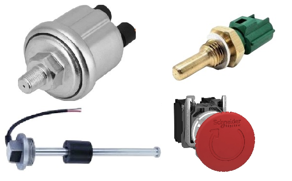
AMF CONTROLLER DC INPUTS
The connector JF is used for the ANALOG and DIGITAL sensor fitted on the engine. You can use various sensors. Default settings allow the use of VDO-CONINENTAL devices. You can change the setup according to your sensors.
| JF-1 INPUT 1 OPTION [ 1 ]
JF-1 INPUT 1 POLARITY [N.O.] |
See Table 9.07 in the installation manual for the available 35 option list. You can select N.O. (normally open) or N.C. (normally closed). These are free programmable digital inputs. You activate one input when you connect it to the battery minus. The inputs are fully protected up to 100V in all polarities. In square brackets, you see the factory setting:
[ 1 ] Immediate Stop [ 26 ] Remote Start [ 12 ] Mains Presence Simulated |
| JF-2 INPUT 2 OPTION [ 26 ]
JF-2 INPUT 2 POLARITY [N.O.] |
|
| JF-3 INPUT 3 OPTION [ 12 ]
JF-3 INPUT 3 POLARITY [N.O.] |
AMF CONTROLLER AC INPUTS
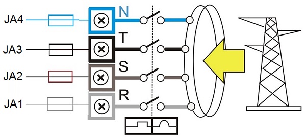
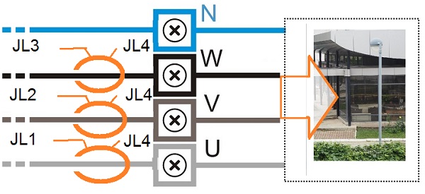
The JA removable plug connects MAINS and GENERATOR voltages, the electrical parameters must fit the range of 80-600V and 20-99HZ. The removable connectors JP and JL connect the CURRENT TRANSFORMERS. Their size must match the EARTH FAULT current sensing and the 3-PHASE GENERATOR nominal load.
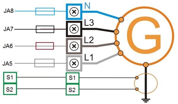
The JA removable plug is used to connect the Mains voltages. Electrical parameters must be in the range of 80-600V and 20-99HZ.
Connect the current transformer on the LOAD side. In this way you will get current measurements all the time. When you set an overload warning or shutdown, only the measurement from the generator will cause the alarm.
HOW DOES AN AMF CONTROLLER WORK?
The AMF controller governs the backup generator and transfers the load to the generator or mains smoothly and with short downtime. After detecting a MAINS failure, the AMF controller starts the engine. It may be cold. It waits for a warm-up: the engine will run offload. After the engine warms up, supposing the generator provides the correct frequency and voltage, the AMF controller transfers the load from the MAINS to the GENERATOR. This could be done via a CONTACTOR-BASED changeover or a MOTORISED-BASED transfer switch, Once the mains have been restored, the AMF controller will disconnect the LOAD for a few seconds and automatically connect the LOAD to the MAINS. After a time delay, the engine is then stopped.
IT CONNECTS THE LOAD TO THE GENERATOR
The AMF CONTROLLER activates the KG (contactor of the generator) using the KM-AUX and KG-PILOT contacts. The KM-AUX are the auxiliary contacts fitted on the body of the utility power contactor (KM). When the KM is open, the KM-AUX contacts enable the KG. The AMF CONTROLLER finally activates the KG via the KG-PILOT relay.
IT CONNECTS THE LOAD TO THE MAINS
The KM contactor connects the LOAD to the MAINS (utility power). The coil of the KM energises via the KG-AUX and KM-PILOT contacts. The KG-AUX auxiliary contacts have a mechanical connection with KG, the contacts close when the KG opens. The KM-PILOT is the utility power control relay. This relay is OFF when the utility power is within the settings. Using the normally closed contacts, we prioritise the utility power in case the AMF controller is damaged or without a supply. In case of utility power failure, the AMF controller energises the KM-PILOT. The KM-PILOT contacts will open the KM. Once the KM is open, the auxiliary contacts KM-AUX will close.
When the AMF CONTROLLER switches the generator to the utility power, the user observes a short ‘power outage’. Normally, it is about 2 seconds. This is the typical behaviour of the automatic transfer switch: BREAK-BEFORE-MAKE.
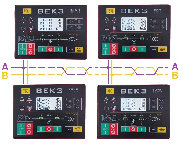
THE "DUAL GENERATOR" AMF CONTROLLER CONNECTION
In addition to the common configuration of a single MAINS-GENERATOR-LOAD arrangement, the AMF CONTROLLER allows the connections of one of two generators to one load. This is not a parallel configuration. It is a basic BREAK-BEFORE-MAKE configuration. In a prolonged power outage, you can use one generator as a master. In case of failure, the second one will supply the load.
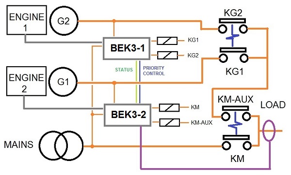
You can set up a timer to supply the load. For example, you can set up 6 hours for each generator.
THE "DUAL LOAD" AMF CONTROLLER CONNECTION
Using this AMF CONTROLLER wiring diagram, you can connect one generator as an emergency standby to serve both loads. This is not a parallel configuration. The generator will supply the only load that suffers from a utility power condition.
It could be only one load or both. The generator will start in case of a utility power failure and stop when the utility power can supply the loads.
The installation of the AMF controller in combination with the RS485 extension board and the motor driver board facilitates the assembly of complex AMF panels. These boards reduce 70% of cabling and miscellaneous components. Non-mention over 50% of workmanship time.

Voltage Supply:
5.5Vdc to 36Vdc, 50-150mA
Protection:
internal 300mA thermal fuse
Dimensions:
192mm X 144mm X 40mm
Panel Cut-out:
187mm X 139mm, indoor operation
Operating temperature range:
-15 deg C up to +70 deg C
Humidity range:
5% up to 95% non-condensing
Weight/IP:
710 grams / IP65
Static output characteristics:
300mA/100Vdc short circuit proof, negative.
Supply output for relays:
Max 1A at V battery minus 1Vdc (short circuit proof)
Mains and Generator voltage input:
Nominal Voltage input: 70 Vac-600Vac
Overvoltage: 4KVac phase to neutral
Measurement precision:
+/- 1%. Input impedance: 2 Mega Ohm
Current transformer input size:
10/5Aac up to 9900/5Aac
Digital inputs Open circuit voltage:
Battery voltage minus 2V - Trigger level: < 2V
Charger alternator monitoring:
Operating voltage up to 36Vdc/3W, accuracy +/- 5%
AMF STUNNING CONTROLLER FEATURES
This is a short list of all AMF controller basic features
80 OPTIONS ON 3 ADJ. OUTPUTS
35 OPTIONS ON 3 ADJ. INPUTS
7-DC OUTPUTS / 6-DC INPUTS
600VAC 3-Ph 4-WIRE MONITORING
1/C.T. EARTH FAULT MONITORING
3/C.T. LOAD MONITORING
OVER 150 ADJUSTABLE SETTINGS
200 EVENTS LOG HISTORY TAGGED BY R.T.C.
14 PUSH BUTTONS
USER-FRIENDLY INTERFACE
GRAPHIC 128x64 LCD DISPLAY
GENERATOR & ENGINE INSTRUMENTS
DRIVES MOTORISED CIRCUIT BREAKERS
REMOTE CONTROL MONITORING
Push the [AUTO] push button until the yellow LED illuminates. The engine starts when the BeK3 detects a Mains failure. The Mains circuit disconnects the LOAD after the [MAINS BREAKER] timing. After the [WARM UP] time, if the voltage and frequency are within the settings, the GCB will close. If the Mains is restored, the MCB will open. The KM will close following a programmed [KM CHANGEOVER] timing. The engine will stop after a [ COOL DOWN ] time. If the engine shuts down because of an alarm, the KM closes independently of the Mains status if the NFPA-110 is on, otherwise, the KM will close only if the parameters of the Mains are within the programmed settings. In AUTO mode, the BeK3 will periodically test the engine if the periodic test is correctly programmed. During the test, the yellow LED AUTO in mode will continue to blink. The BeK3 can start and stop the engine if the remote control is activated.
THE TEST MODE
Press and hold the [AUTO] push button, and the yellow LED blinks. In a power outage, the AMF controller starts the engine and transfers the load to the generator. To exit the TEST mode, push the [AUTO] push button shortly or select another mode of operation.
THE MANUAL MODE
Push the [MAN] pushbutton to select the MAN mode. Push one of the [I-START] push buttons until the engine starts. The display automatically loads the ‘ENGINE STATUS PAGE’ with information about the start sequence. During cranking the Be-K3 turns off the light of the display.
The green engine's LED on the engine drawing turns on when the engine is running. Wait until the green LED Generator Available turns on. Push the [ KG ] push button to close the generator contactor. To transfer the load to the Mains wait for the Green Light Mains available. Push the [ KM ] pushbutton: the KG will open and KM will close after a 2-second delay; the programmable changeover timer works only in AUTO mode. Push one of the [0-STOP] push buttons to stop the engine. The [STOPPING] message will follow on the display. If the engine has already stopped, it is possible to reset the stop sequence by pressing the [0-STOP] pushbutton.
THE OFF MODE
Push and hold, for 2-3 seconds, the [ 0-STOP ] pushbutton: you turn OFF the Be-K3 and clear the fault alarms. You are allowed to program the parameters or modify settings. Push the [ MAN ] or [ AUTO-TEST ] pushbutton on the front panel to turn the AMF CONTROLLER on.
AMF CONTROLLER REMOTE CONTROL MONITORING
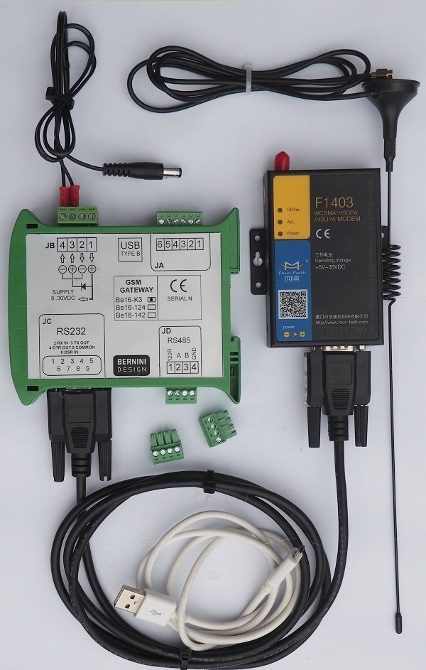
The BeK3 automatic mains failure controller features an RS-485 serial interface capable of supporting Modbus RTU. We offer GSM remote monitoring, TCP/IP connection, and Modbus remote monitoring.

The simplest way to monitor your standby generator is by using SMS, which is the most stable and reliable solution. The GSM system is connected to the AMF controller via RS-485. In other words, you can place the GSM kit as far as 1000m from the panel. This allows you to put the modem in a good position. This will optimise the quality of GSM communications.
BY ADDING THE BE16-K3 GSM GATEWAY AND A 4G-5G MODEM, YOU WILL GET FULL CONTROL OF YOUR POWER GENERATOR VIA A SET of SMS
The table lists the SMS commands that will allow you full access to your standby system
| STATUS | It sends a request to read the engine's status and mode of operation and to read the power supply of the BE16 module. |
| ALARM | It sends a request to get information about active alarms. You will receive the message ‘NO ALARMS’ if there is no active alarm. |
| GENP | It sends a request to read all the instruments related to electric power. |
| GENV | It requests to read the generator's voltages, currents and frequency. |
| MAINS | It sends a request to read the voltages and frequency of the Mains. |
| ENGINE | It requests to read Battery Voltage, Speed, Oil Pressure, Fuel% %, Temperature, and h-meter. |
|
CLEAR (*) |
It clears a warning or it cancels a shutdown. Please note that in case of a shutdown, the Be16 will force the BeK3 to enter the OFF mode of operation. After that, you are required to take action. Otherwise, the controller will remain in OFF mode of operation. |
| OFF | It commands the BEK3 to enter the OFF mode of operation and eventually shuts down the engine. The command is ignored if the BeK3 controller is in manual mode of operation. |
| AUTO | It forces the BeK3 to enter the AUTO mode of operation (only if it was in OFF mode). You cannot change a MODE of operation if the BeK3 is locally in MANUAL mode. So, this command is ignored in the MANUAL mode of operation |
| TEST | It makes the BeK3 start the engine. If the option [KG TEST CONTROL] (see section 8.03 of the OEM manual) is set to [ON], when the electrical parameters are within programmed settings, the BeK3 will transfer the LOAD to the generator. This function works only if the BeK3 is in the AUTO mode of operation. Send the SMS ‘AUTO’ to stop the engine or quit the function. The BeK3 will enter the AUTO mode of operation. If all conditions are met, the BeK3 stops the engine. |
AMF CONTROLLER TCP-IP MONITORING OPTION
If you are comfortable with TCP_ip protocol we offer a TCP-ip embedded server. You will no longer dependent on third party services. You buy your own server an directly configure to reach your goals in minutes.
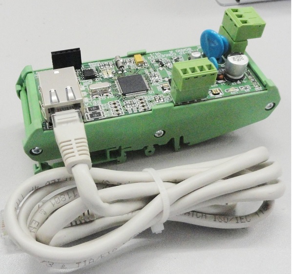
Simply connect the Ethernet cable to your roter on one side and the RS485 cable on the other side... You can place the AMF controlleer as far as 1000m by using a simple twiested cable. Follow our instructions and you can connect any device on the internmet.
AMF CONTROLLER LONG-TERM RELIABILITY
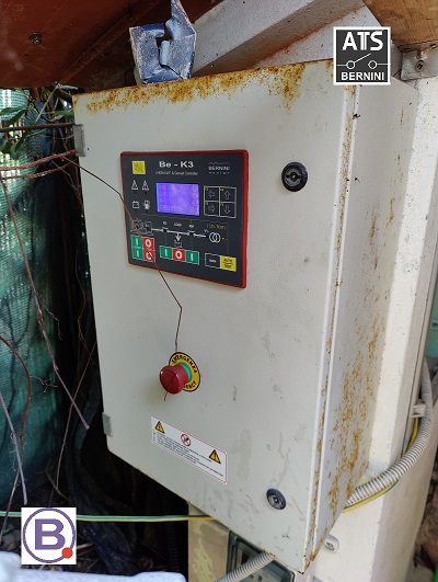
This is what a controller looks like after 12 years of service, day and night at a beach resort
PURCHASE NFPA-110 COMPLIANT 15-800kVA AMF PANELS
Thanks to the high-quality materials and silicon gasket, this is how the AMF controller looks after 12 years of full exposure to elements.
12 years of exposure to the elements
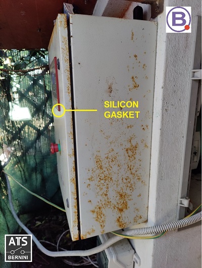
The customer asked us to replace the metal cabinet but we recommended refurbishing it with a special coating resin. The control panel is fully functional. A replacement of the cabinet is time-consuming.
12 years of exposure to the elements
After seeing the shocking images of the panel, you will experience a bigger shock looking at the interior of this AMF panel.
12 years of exposure to the elements
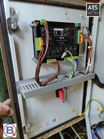
As you can see, the AMF controller seems brand new. There is no particular evidence of rust or damage. It works perfectly.
Bernini Design Srl
Industrial Park
46035 Ostiglia (Italy)
bernini@bernini-design.com
+39 335 70 77 148