HOW TO CONFIGURE THE KIT?
You do not need a computer or a complex device. The Be148 accepts configuration via SMS supposing you follow the instructions in the user manual. The overall configuration may only require 3 minutes.
WHAT KIND OF GENERATOR I CAN USE WITH IT?
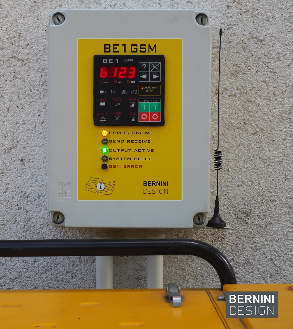
To get the best results, we recommend that you interface the Be148 with a good auto-start module. In this case, it no longer matters the kind of generator! You will directly connect the Be148 output to the remote start input of the auto-start module. You can use a D.I.Y. auto-start module made of discrete relays. You may also consider the option to refurbish your old generator with a professional auto-start KIT module BE1
GSM START-STOP INSTALLATION MANUAL
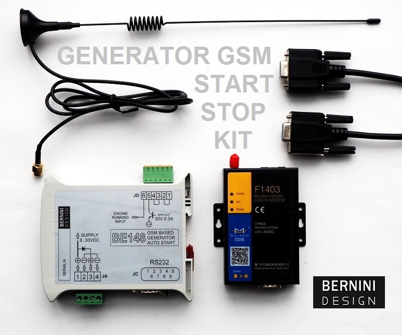
The BE148 is GSM controlled START-STOP kit. The kit includes the Be148 rail-mount relay and 5-band GSM modem. The kit does include all cables, antenna and removable connectors. It is suitable to start and stop a generator by using a mobile phone. The Be148 can detect if the engine is running and can send the ‘STARTING FAILURE’ alarm on your mobile. The Be148 is easily configurable using your mobile phone.
BE148 GENERATOR REMOTE GSM RELAY SETUP
Follow the instructions.
[1] Unpack the box. The content must include the Be148 rail-mount relay with 4-pole and 6-pole connectors, the RS232 cable, the antenna and the modem power supply cable.
[2] Insert the SIM into the modem. Make sure the SIM has the PIN disabled. If not, you are required to disable it by using a mobile phone. Insert the screw-type antenna connector.
[3] Connect the modem F1403 to Be148 relay by using the RS232 cable.
[4] Unplug the 4-pole power supply and 6-pole connectors from the Be148.
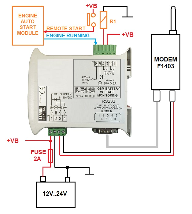
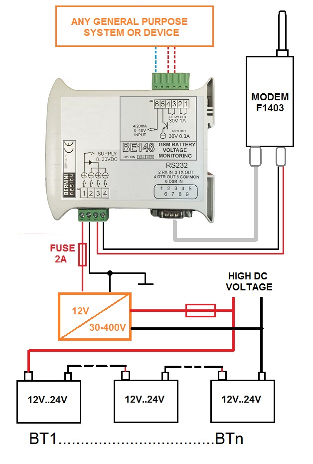
[5] Make the connections as indicated in the recommended wiring diagram
[6] Connect the wires of the battery to terminal 1 (PLUS) and terminal 2 (MINUS). You can use the battery of the engine via a 5 Amp fuse. This protects the wires in case of a short circuit. Do not turn on the supply.
[7] Verify, on the 4-pole connector, that terminal 3 (PLUS-red wire) and terminal 4 (MINUS-black wire) are firmly connected to the modem supply cable. Plug the jack into the modem and the 4-pole connector to Be148.
[8] Insert the 6-pole connector if the functionality of the generator start-stop circuit has been carefully tested. Connect the battery or your available DC power supply.
[9] As soon as you connect the DC supply, the BE148 will turn all LED indicators on for a second. After that, the DL2 illuminates to indicate the modem initialization sequence for about 2 minutes.
[10] The green indicators ‘Power’ and ‘Online’ on the modem will turn on as well. The green indicator ‘Act’ will blink from time to time. The green LED and ‘Online’ will start blinking as soon as the modem is connected to the GSM network. This will take approximately 2 minutes.
[11] When the modem is fully active, the green indicator DL1 turns on. At the same time, the DL2 will turn OFF. If the red indicator DL5 is permanently on, the MODEM fails to work. If DL5 blinks, the power supply is lower than 8Vdc.
THE GENERATOR REMOTE GMS SMS SYNTAX
[A] When the DL1 indicator is on, type on your mobile BE148 *PHONE NUMBER#.Type a blank space after Be148. The (*) is the asterisk symbol. The (#) is the hash symbol. The (PHONE NUMBER) is your mobile phone number. The system accepts either lower or upper-case letters. Send the SMS to the SIM card of the modem.
[B] After a few seconds you will receive the response SMS in the form BE148 PHONE SAVED. Each time the kit sends or receives an SMS, the DL2 turns on for just a second.
[C] Remove the power supply for about 5 seconds, then reconnect the DC power supply.
[D] After 2 minutes you must receive the SMS POWER ON, BE148 V1,14, SUPPLY 12.0V NOT RUNNING, OUT OFF. The (V1,14) may vary depending on the software version, and The (12.0) may differ depending on the supply voltage.
[E] To start the generator send the SMS BE148 START. The Be148 will close the contacts JD3 and JD4 to start the engine.
[F] If the engine starts and Be148 detects the ‘ENGINE RUNNING’ status via the JD6 input, you will get the SMS BE148 OUT ON! RUNNING!. If the engine will not start within 120 seconds, the Be148 shuts down the output and turns on the red indicator DL5 (see NOTE 1).
[G] Should the engine fail to run after a successful start sequence, you will receive the message NOT RUNNING! FAILURE!. In this case, the Be148 opens the contacts JD3-JD4 in a way to disable the engine start circuit and turns on the red indicator DL5 (see NOTE 1).
[H] At any given time, you can send the SMS BE148 STATUS. If the engine is not running, the system will respond with the following SMS BE148 STATUS: SUPPLY XX.V, NOT RUNNING, OUT OFF. If the engine is running normally, the system will respond with the following SMS BE148 STATUS: SUPPLY XX.XV, RUNNING, OUT ON
NOTE 1
IN CASE YOU DO NOT MONITOR THE ENGINE RUNNING STATUS, WE RECOMMEND YOU ACTIVATE THE DIP-SWITCH 4. THIS FUNCTION DISABLES THE STARTING FAILURE ALARM. YOU MAY RECEIVE NOTIFICATIONS ABOUT THE ‘ENGINE RUNNING’ STATUS, BUT BE148 WILL NOT SHUT DOWN THE OUTPUT IN CASE OF STARTING FAILURE.