WHAT IS AN AMF CONTROLLER?
An AMF controller governs all functions of a standby generator. It automatically manages the connection assignment of the LOAD to MAINS or GENERATOR. The AMF controller is the core of AMF panels.
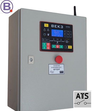
THE BEK3 AMF CONTROLLER
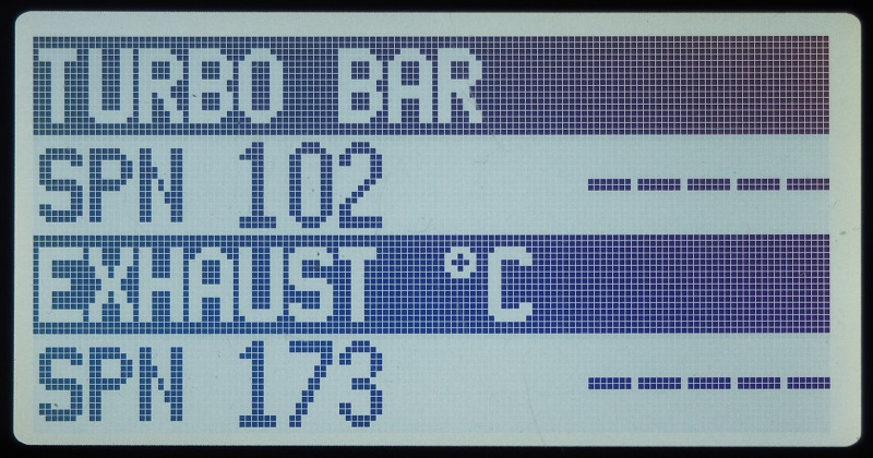
A 128X64 graphic display, operating in a temperature range between -15°C and +50°C, indicates parameters, alarms, and miscellaneous functions. The AMF controller measurements include Vac, Aac, Vdc, kVA, kVar, kW, Energy, Pdf, Hz, hour count, R.p.m., Oil Pressure, Engine Temperature, Battery Vdc (Engine), and Fuel Level. The BeK3 complies with NFPA-110 / NFPA-99 specifications.
AMF CONTROLLER CANBUS
Regarding engines with ECU, this AMF controller features a fully isolated CANbus. It supports the J1939 protocol.
AMF CONTROLLER MODBUS-RTU
The Bek3 AMF controller features an RS485 powerful serial interface. The RS485 can drive a 1000m twisted pair and 127 nodes. It completely supports the MODBUS-RTU protocol.
We supply accessories and serial interface adapters with free-of-charge remote monitoring software.
BLUETOOTH-BASED I/O 16 CHANNELS INTERFACE BOARD
Save money and time. We have an environmentally friendly solution. With our AMF controller, you save as much as 50% of cables.

The extension board allows you to expand the INPUT/OUTPUT of the BeK3 AMF controller. The basic features include 2 fully isolated RS485 serial interfaces, and 2 CANBUS ports with 16 dry-contact relay outputs. 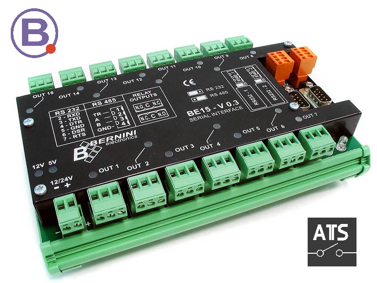
The extension board communicates via Bluetooth.
A MASTERPIECE AMF CONTROLLER
Bernini Design developed the BeK£ AMF controller. It features a multiprocessor architecture and a multilayer PCB.

The programmable parameters are stored in 3 different areas of the non-volatile memories. Bernini Design developed the all APPS required from the AMF controller.
AMF CONTROLLER DESIGNED FOR BASE TRANSCEIVER STATIONS (BTS)
A standby generator installed in the base transceiver station (BTS) requires extraordinary features. The AMF controller must withstand a temperature range between -30 degrees Celsius and +75 degrees Celsius. It is quite clear that in this case only ORGANIC LED and SOLID STATE LED are allowed.
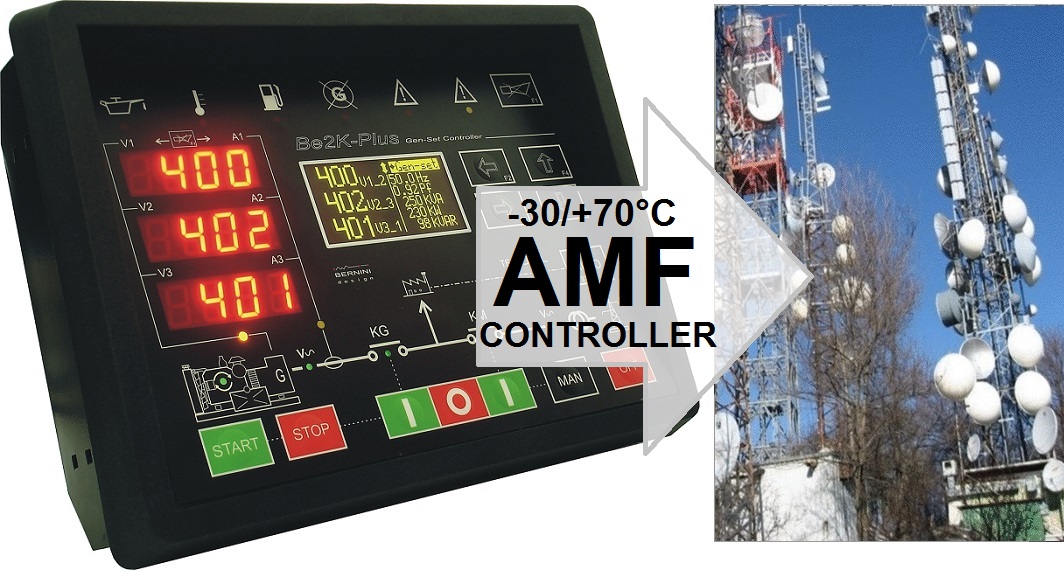
The second mandatory requirement is a multiprocessor redundant architecture. Last but not least a fully independent watchdog system must override the AMF controller in case of a software crash. The Be2K-PLUS satisfy the above requirements and much more. Visit the page
AMF PANELS PRICE
If your business is the installation of turnkey standby generators we recommend that you browse the price list of our AMF panels. We offer remote monitoring solutions free of charge. Depending on the characteristics of your system, we install contactor-based changeovers or motorized switch-based changeovers.
AMF CONTROLLER PRICE
If your business is to make AMF panels you can purchase a sample of the BeK3 AMF controller. You can evaluate the product.
MAKE YOUR OWN AMF PANEL TODAY
You can pay online or ask for a Proforma Invoice and pay via bank transfer
249€
FREE-SHIPPING WORLD-WIDE
SUPPORT
+39 335 70 77 148
MAYBE YOU ARE INTERESTED IN TWO PIECES. THERE YOU ARE OUR OFFER
PURCHASE 2 PCS
199€/each
FREE-SHIPPING WORLD-WIDE
You can pay online or ask for a Proforma Invoice and pay via bank transfer
SUPPORT
+39 335 70 77 148
WE APPLY SPECIAL DISCOUNTS OF 20% 40% FOR BULK ORDERS
THE BEK3 IS A "ROCK SOLID " AMF CONTROLLER WITH AN ENCLOSURE MADE OF STEEL
We do not use plastic materials for making RELIABLE AMF controllers. The enclosure of the BeK3 controller is made of zinc double-coated steel. Zinc is a heavy element, and when alloyed with other metals, it provides better corrosion resistance, stability, dimensional strength and impact strength.
The rear cover made of metal is the best solution for shock-proof equipment. It is an excellent protection against electromagnetic fields by enclosing the 32-bit processor into a Faraday cage. The BeK3 AMF controller provides an extraordinary advantage over competitors' plastic-based enclosures.
INGRESS PROTECTION IEC60529 SILICON GASKET UV-PROOF
The BeK3 AMF controller, thanks to a silicon gasket, is IP65-compliant.

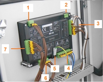
INSIDE A BEK3-BASED PANEL OVERVIEW
[1] Power supply [2] Modbus port [3] Digital / Analog Inputs [4] Generator & Utility power connections [5] Protection Ground [6] Current transformers
THIS IS HOW IT LOOKS LIKE A CONTROLLER AFTER 12 YEARS OF SERVICE DAY AND NIGHT ON A BEACH RESORT
Thanks, for the high-quality materials and silicon gasket, this is how it looks like the BeK3 AMF controller after 12 years of full exposition to elements.
12 years of exposition to the elements
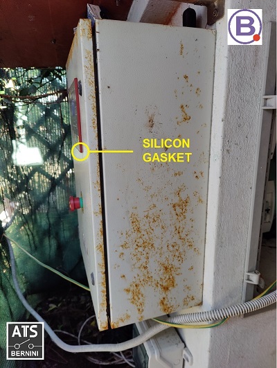
The customer asks us to replace the metal cabinet. We recommended to refurbish it with a special coating resin. The control panel is fully functional. A replacement of the cabinet is time-consuming.
12 years of exposition to the elements
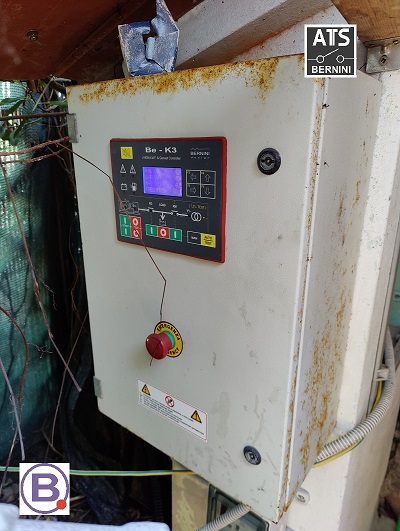
After seeing the shocking images of the panel, you will experience a bigger shock looking at the interior of this AMF panel.
12 years of exposition to the elements
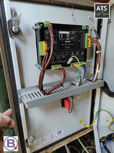
As you can see it seems brand new. There is no particular evidence of rust or damage. It works perfectly.
12 years of exposition to the elements
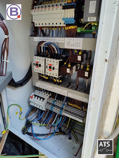
Having written that, let's go on with the presentation of this extraordinary AMF controller
AMF WIRING DIAGRAM DESCRIPTION
The BeK3 AMF controller governs the system and transfers the load to the generator or mains smoothly and with short downtime. This AMF panel wiring diagram illustrates the connections of the BeK3 AMF controller. It monitors the parameters of the mains and automatically starts the engine via relays. Once the generator provides the correct frequency and voltage, the controller transfers the load from the mains to the generator.
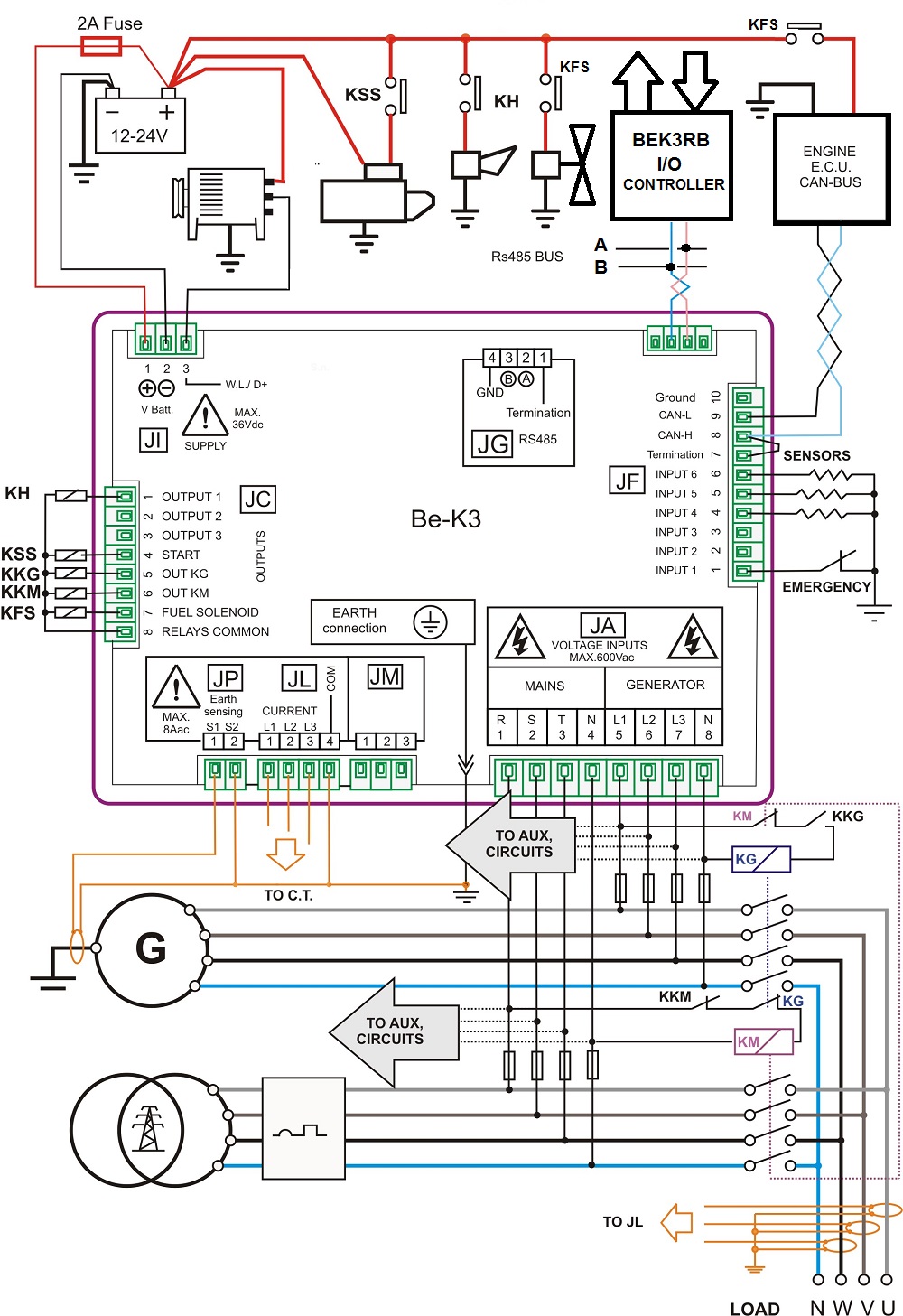
This happens after a mains failure programmed delay (seconds, minutes or hours). When the engine is cold, the AMF controller waits for a warm-up. The engine will run offload. Once the mains has been restored, the AMF controller will connect the load to the mains automatically. After a time delay, the engine is then stopped.
HOW DOES IT WORK IN DETAILS THE AMF CONTROLLER
The BeK3 controller closes the KM-AUX and KG-PILOT contacts to activate the KG (contactor of the generator). In this way, the LOAD is connected to the generator. The KM-AUX are the auxiliary contacts fitted on the body of the utility power contactor (so-called KM). When the KM is open, the KM-AUX contacts enable the KG. The AMF controller activates the KG via the KG-PILOT relay. The N and L3 of the generator supply the coil of the KG. When switching the generator to the mains, the user observes a short ‘power outage’. Normally it is about 2 seconds. This is the typical behaviour of the automatic transfer switch: BREAK-BEFORE-MAKE.
AMF CONTROLLER MAINS-LOAD
The KM contactor connects the LOAD to the MAINS. The coil of the KM energizes using the KG-AUX and KM-PILOT contacts. The KG-AUX auxiliary contacts have a mechanical connection with KG. The contacts close when the KG opens. The KM-PILOT is the utility power control relay. This relay is OFF when the mains is within the settings. In this case, the COIL of the KM is supplied via the N and L3 of the MAINS. By using the normally closed contacts, we are sure to provide priority to the mains in case the AMF controller is damaged or without supply. In case of mains failure, the AMF controller energizes the KM-PILOT. The KM-PILOT contacts will open the KM. Once the KM is open, the auxiliary contacts KM-AUX will close. This is one of the mandatory conditions to close the KG (the KM must be open in the first place).
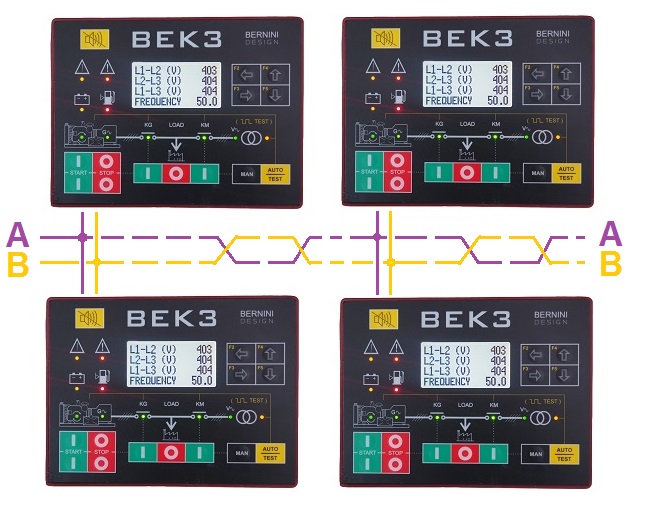
AMF CONTROLLER DUAL GENERATOR SINGLE LOAD CONFIGURATION
With this AMF panel wiring diagram, you can connect two generators as an emergency standby to one load. This is not a parallel configuration. It is a basic BREAK-BEFORE-MAKE configuration. In a prolonged power outage, you can setup one generator as a master. In case of failure, the second one will supply the load.
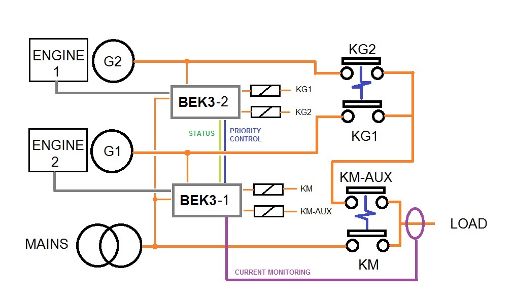
You can set up a timer to supply the load. For example, you can set up 6 hours for each generator. In t
DUAL LOAD WITH A SINGLE GENERATOR
By using this AMF panel wiring diagram, you can connect one generator as an emergency standby to serve both loads. This is not a parallel configuration. The generator will supply the only load that suffers a utility power condition.
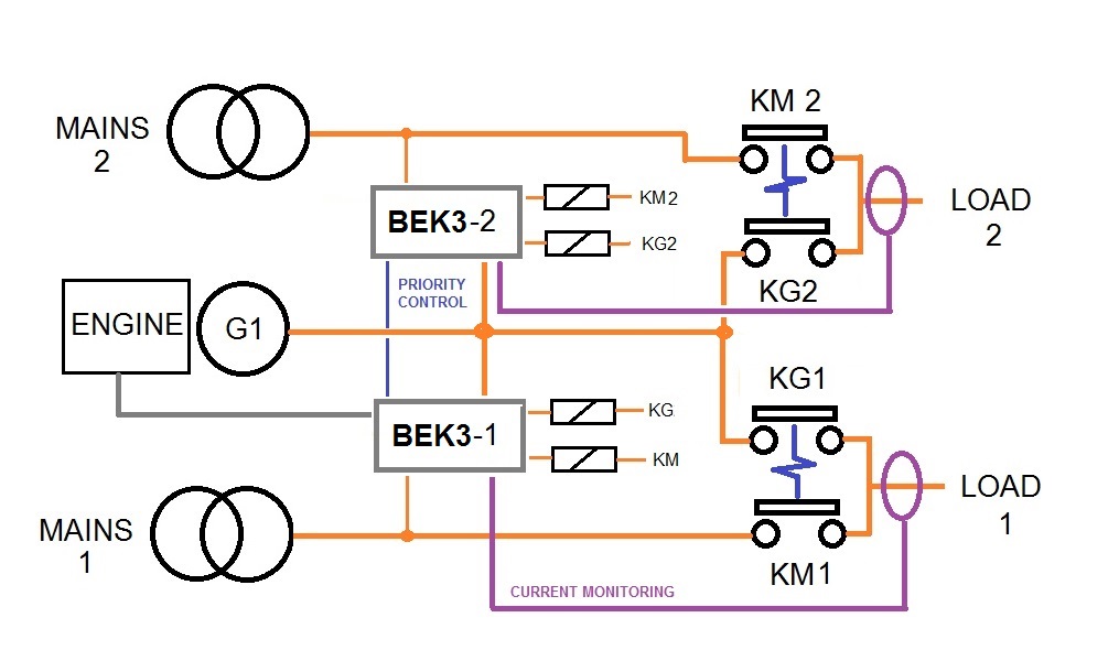
Could be only one load or both. The generator will start in case of one utility power failure and stop when the utility power can supply the loads.
A USER-FRIENDLY AMF CONTROLLER
[1] Warning indicator [2] Shut down indicator [3] Battery alarm [4] Fuel Alarm [5] Engine is running [6] Generator Voltage [7] Engine start button [8] Engine stop button [9] AMF manual control buttons
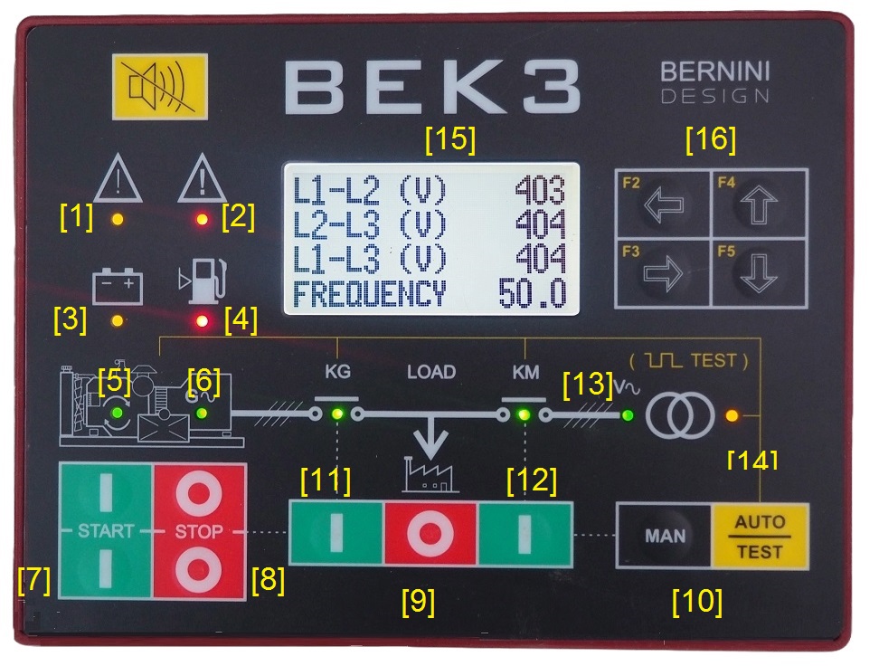
[10] Mode of operation selection [11] Generator contactor [12] Utility power contactor [13] Utility power voltage [14] Auto mode indicator [15] LCD [16] Navigation buttons.
AMF CONTROLLER GENERAL FEATURES
80 OPTIONS FOR EACH ADJUSTABLE OUTPUT
5-PROGRAMMABLE LE RELAY OUTPUTS
35 OPTIONS FOR EACH ADJUSTABLE INPUT
6-PROGRAMMABLE DIGITAL INPUTS
12-INPUT/12-OUTPUT EXPANSION BOARD
200 EVENTS LOG HISTORY TAGGED BY R.T.C.
600VAC 3-PHASE VAC MONITORING
EARTH FAULT MONITORING
OVER 150 ADJUSTABLE SETTINGS
14-BUTTON INDUSTRIAL CONTROL PANEL
GRAPHIC 128X64 LCD DISPLAY
SUNLIGHT READABLE DISPLAY
GENERATOR INSTRUMENTS
ENGINE INSTRUMENTS
BLUETOOTH-BASED EXTENSION BOARD
DRIVES MOTORIZED CIRCUIT BREAKERS
WIDE TEMPERATURE OPERATING RANGE
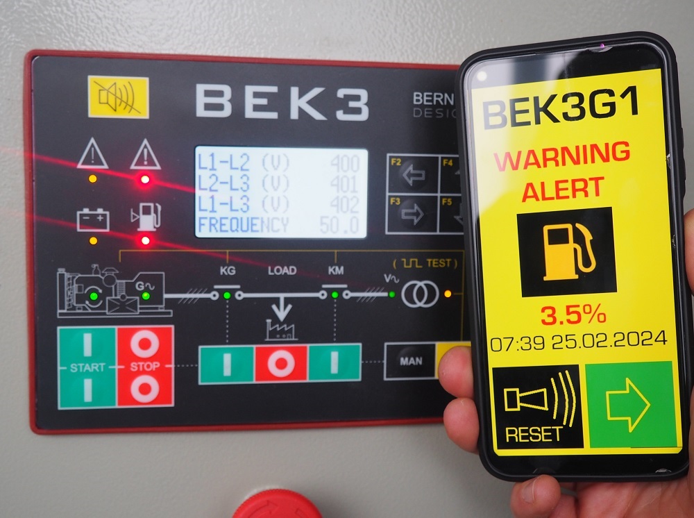
LOOKING FOR A POWER GENERATOR GSM MONITORING?
The BeK3-PLUS automatic mains failure controller features an RS485 serial interface capable of supporting Modbus RTU. We offer GSM remote monitoring, TCP/IP connection, and Modbus remote monitoring.
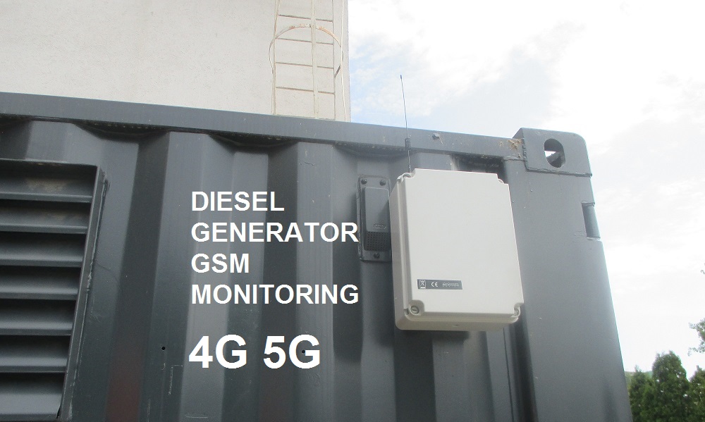
The most simple way to monitor your standby generator is by using SMS. This is at today the most stable and reliable solution.
READ MORE ABOUT GSM MONITORING
BY ADDING THE BE16-K3 GSM GATEWAY AND A 4G-5G MODEM YOU WILL GET FULL MODBUS CONTROL OF YOUR POWER GENERATOR VIA A SET OF SMS COMMANDS
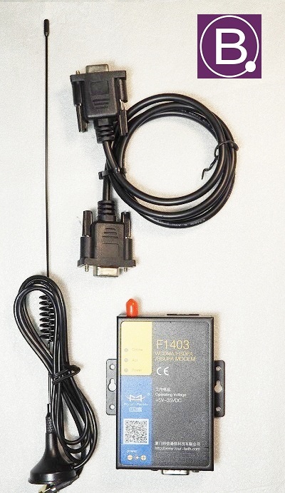
PURCHASE OF THE BE16-K3 GSM SYSTEM DOES INCLUDE THE 4G-5G F1403 INDUSTRIAL-GRADE MODEM.
PURCHASE THE KIT
399€/each
FREE-SHIPPING WORLD-WIDE
DELIVERY TIME 30 DAYS
You can pay online or ask for a Proforma Invoice and pay via bank transfer
SUPPORT
+39 335 70 77 148
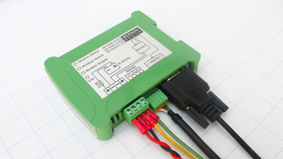
THE F1403 MODEM IS INCLUDED IN THE KIT TOGETHER WITH ALL ACCESSORIES NEEDED TO IMPLEMENT A GSM POWER GENERATOR MONITORING SYSTEM
In the following table you can see the basic SMS commands that will allow you full access to your standby system
| STATUS | It sends a request to read the engine's status and mode of operation and to read the power supply of the BE16 module. |
| ALARM | It sends a request to get information about active alarms. In case there is no active alarm, you will receive the message ‘NO ALARMS’. |
| GENP | It sends a request to read all instruments about electric power. |
| GENV | It sends a request to read the voltages, currents and frequency of the generator. |
| MAINS | It sends a request to read the voltages and frequency of the Mains. |
| ENGINE | It sends a request to read Battery Voltage, Speed, Oil Pressure, Fuel %, Temperature, and h-meter. |
|
CLEAR (*) |
It clears a warning or it cancels a shutdown. Please note that in case of shutdown, the Be16 will force the BeK3 to enter the OFF mode of operation. After that, you are required to take an action. Otherwise, the controller will remain in OFF mode of operation. |
| OFF | It commands the BEK3 to enter the OFF mode of operation and eventually shuts down the engine. The command is ignored if the BeK3 controller is in manual mode of operation. |
| AUTO | It forces the BeK3 to enter the AUTO mode of operation (only if it was in OFF mode). You cannot change a MODE of operation if the BeK3 is locally in MANUAL mode. So, this command is ignored in the MANUAL mode of operation |
| TEST | It makes the BeK3 start the engine. If the option [KG TEST CONTROL] (see section 8.03 of the OEM manual) is set to [ON], when the electrical parameters are within programmed settings, the BeK3 will transfer the LOAD to the generator. This function works only if the BeK3 is in the AUTO mode of operation. To stop the engine or quit the function, send the SMS ‘AUTO’. The BeK3 will enter the AUTO mode of operation. If all conditions are met, the BeK3 will stop the engine. |
AMF CONTROLLER SPECIFICATIONS
Supply voltage:
5.5Vdc to 36Vdc, 50-150mA
Protection:
internal 300mA thermal fuse
Dimensions:
192mm X 144mm X 40mm
Panel Cut-out:
187mm X 139mm, indoor operation
Operating temperature range:
-25 deg C up to +70 deg C
Humidity range:
5% up to 95% non-condensing
Weight:
710 grams
Ingress Protection:
IP40 (option IP65)
General design:
ECC 89/336, 89/392, 73/23, 93/68, IEC 68-2-6
Certification:
CE
Static output characteristics:
300mA/100Vdc short circuit proof, negative.
Supply output for relays:
Max 1A at V battery minus 1Vdc (short circuit proof)
Mains and Generator voltage input:
Nominal Voltage input: 70 Vac-600Vac
Overvoltage: 4KVac phase to neutral
Measurement precision:
+/- 2%. Input impedance: 2 Mega Ohm
Current transformer input size:
10/5Aac up to 9900/5Aac
Maximum admissible permanent current:
7Aac
Measurement precision:
+/- 2%. Internal resistance: 0.05 Ohm
Digital inputs Open circuit voltage:
Battery voltage minus 2V - Trigger level: < 2V
Charger alternator monitoring:
Operating voltage up to 36Vdc/3W, accuracy +/- 5%
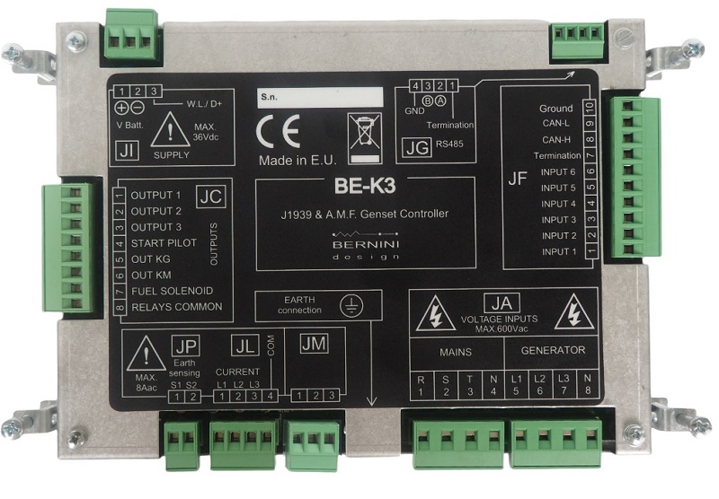
THE BEK3 AMF CONTROLLER OUTPUTS
On the removable connector JC you are required to wire the auxiliary relays. The BeK3 provides a common supply rail (JC8) suitable for automotive relays. It features over-voltage protection, short circuit protection, and EMI protection. You are required to use 90-200 OHM DC coil relays (12 V or 24 according to your engine battery). The removable connectors JP and JL are provided for the connection of the CURRENT TRANSFORMERS suitable for the current monitoring of the EARTH FAULT and the current monitoring of the 3-PHASE GENERATOR. Use suitable current transformers for your application.
MAINS & GENERATOR CONNECTIONS
The JA removable plug is used to connect the Mains & Generator voltages. Electrical parameters must be in the range of 80-600V and 20-99HZ. The version BeK3-400Hz is normally available on request for Aircraft Ground Support Equipment. Protection fuses are highly recommended for cable protection. The connector JF is used for the ANALOG and DIGITAL sensor fitted on the engine.
CANBUS & MODBUS CONNECTIONS
CANBUS terminals are also provided on this connector (your ECU must be SAE J1939 compliant). The removable plug JG allows you the connect the RS485 serial interface. The internal driver will allow you to use a 1000 m cable length.
AUTO MODE OF OPERATION
The AMF controller BeK3 can start the engine at any time. When servicing the engine, disconnect the battery and battery charger. We recommend that warning signs be placed on equipment indicating the above.
Push the [AUTO] push button until the yellow LED illuminates. The engine starts when the BeK3-PLUS detects a Mains failure (see section 9.01 for settings). The circuit breaker of the Mains opens after the [MAINS BREAKER] timing. After the [WARM UP] time if the voltage and frequency are within the settings, the circuit breaker of the Generator will close. If the Mains restores, the KG will open. The KM will close following a programmed [KM CHANGEOVER] timing. The engine will stop after a [ COOL DOWN ] time. If the engine shuts down, because of an alarm, the KM closes independently of the Mains status if the [ NFPA-110 ] is on, otherwise, the KM will close only if the parameters of the Mains are within the programmed settings. In AUTO mode, the BeK3 will periodically test the engine if the periodic test is correctly programmed. During the test, the yellow LED of the AUTO mode will continue to blink. In AUTO mode, the BeK3 can start and stop the engine if the remote control is activated (Table 9.07 options [25] or [26]).
TEST MODE
Push and hold the [AUTO] push button until the yellow LED starts blinking. The BeK3-PLUS will start the engine and transfer the load to the Generator only in case of Mains failure if not otherwise programmed by the parameter [KG TEST CONTROL] (section 8.03). To exit the TEST mode, push the [AUTO] push button shortly or select another mode of operation.
BERNINI DESIGN SRL
ITALY
Industrial Park
46035 OSTIGLIA
SUPPORT
+39 335 70 77 148