TYPE SIMPLE SMS TO START-STOP AND MONITOR YOUR GENERATOR
GSM GENERATOR CONTROL PANEL INSTRUCTION MANUAL
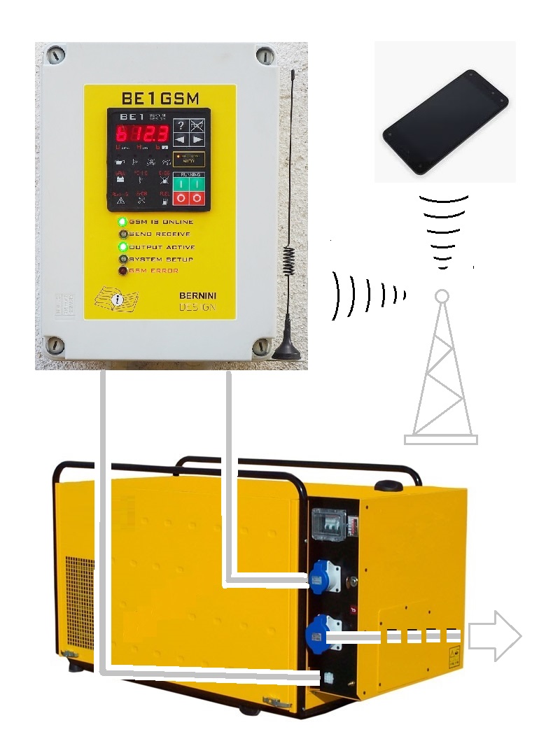
The BE1 GSM panel includes the Be1 generator controller, the Be148-1 SMS gateway module, a GSM modem, cables, an antenna and interface boards with removable connectors. It is suitable for starting, stopping, and monitoring a generator or engine-driven machinery.
NO MORE HEADACHE IN LOOKING FOR COMPONENTS AND CONTROLLER TO REMOTELY CONTROL YOUR GENERATOR USING YOUR MOBILE
READ MORE ABOUT BE1 GENERATOR CONTROLLER
THE BE1 GSM PANEL INCLUDES ALL YOU NEED: GENERATOR CONTROLLER, GSM GATEWAY AND A RELAY BOARD AND
BE1-148 SMS GATEWAY INSTRUCTION MANUAL
OUR BASIC DESIGN CONCEPT IS ONLY ONE: KEEP IT SIMPLE
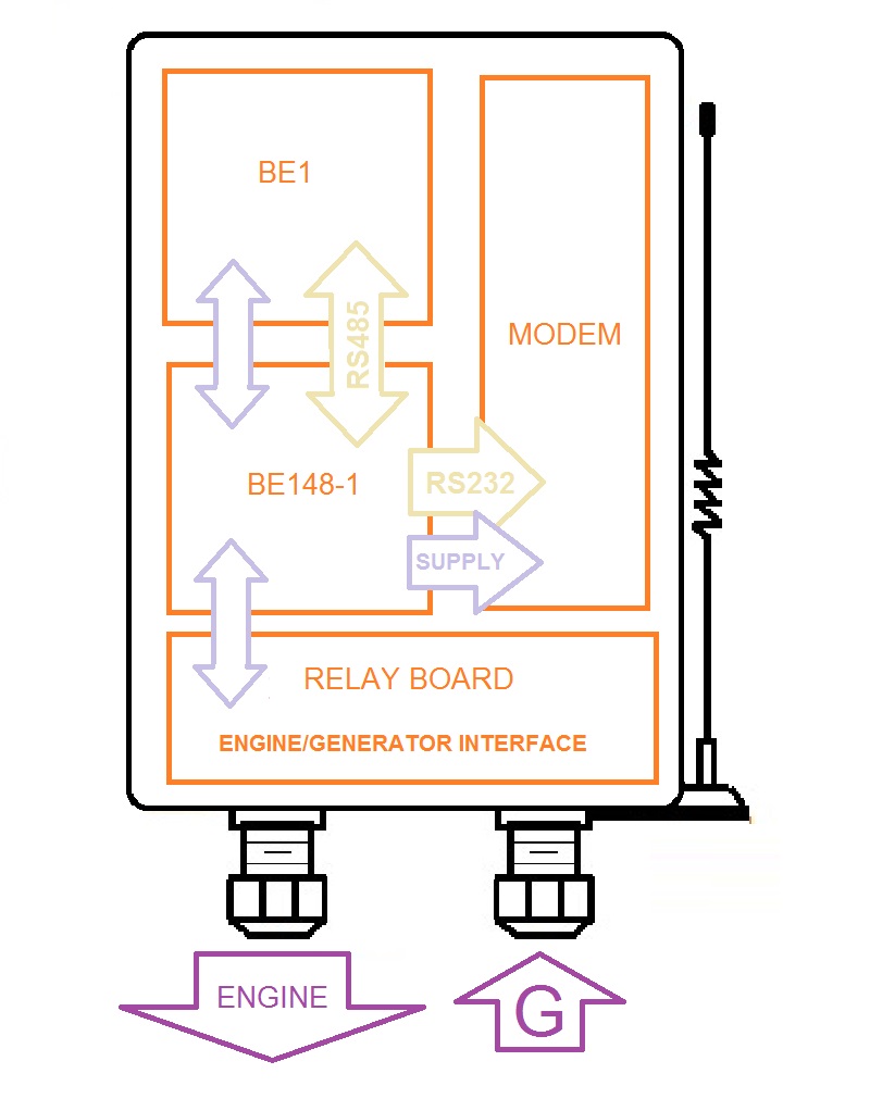
The panel consists of basic ingredients: a Be1 generator controller, a general-purpose interface relay board, a state-of-art GSM Be148-1 gateway and a multiband MODEM.
USER-FRIENDLY EASY TO INSTALL
Unpack the panel. Loose a little of the 4 fixing screws. Remove the 2 screws on the right side. Loose the two screws on the left side in a way that the door of the panel can pivot toward the left side. Fix the panel on the wall. Make the connection to your generator. Install a normal SIM card for the internal MODEM. Send the configuration SMS to the MODEM: The system will be functional in 2 minutes.
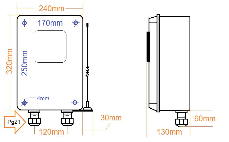
Position the GSM panel onto the wall in the desired location. Mark the hole location on the wall (250mm/vertical and 170mm horizontal pattern). Connect your generator as indicated in the Be1 recommended wiring diagram section 17 of the Be1 installation manual. When in doubt, contact us first for information. Before connecting the DC supply connect in series a fuse of a suitable size to protect the cables from short circuits. Make sure the battery is 12V nominal.
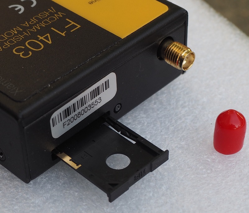
THE ALL POWER OF THE F1403 MODEM IN YOUR HAND
The modem inside the Be1 GSM panel requires a simple GSM SIM card, The Be148 SMS gateway will bidirectionally translate the SMS from the GSM network in MODBUS-RTU commands. This will allow you to receive feedback about the execution of your commands.
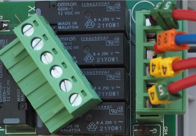
IT INTERFACES THE ENGINE VIA POWERFUL RELAYS
Inside the BE! GSM panel, an interface board that supports power relays. These relays are committed to start and stop the engine. Two fully configurable relays can be used for various special functions as described in the "PROGRAMMABLE OUTPUT" section of the user manual.
INTERNAL REMOVABLE TERMINAL BLOCKS
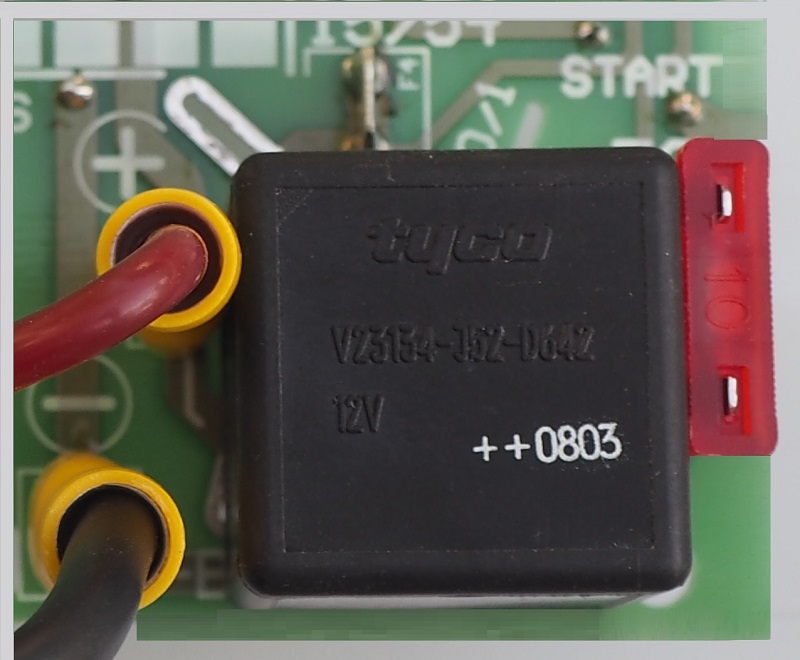
Internal connections made of removable terminal blocks will facilitate service or troubleshooting. This will avoid mistakes in reconnecting the wires.
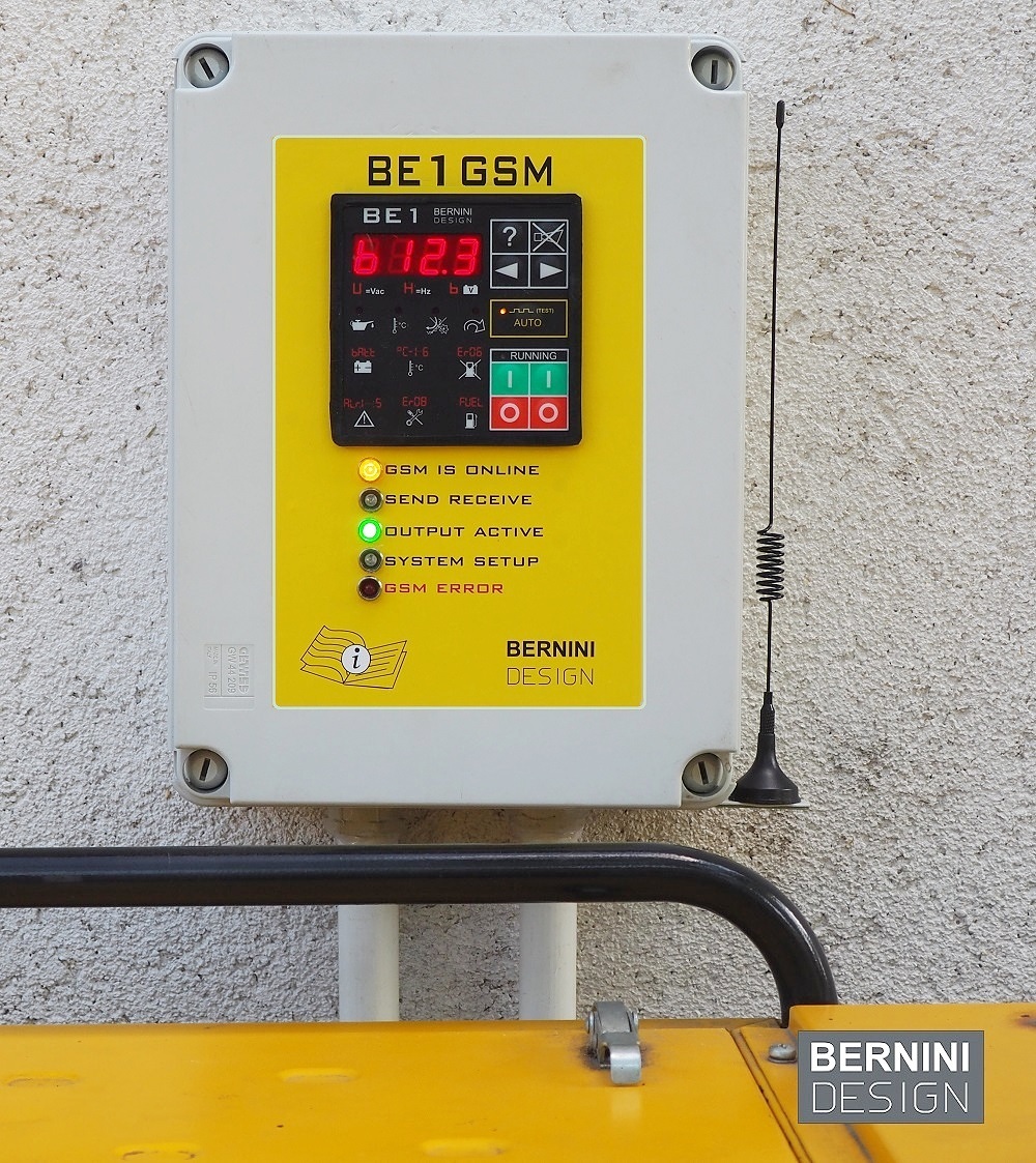
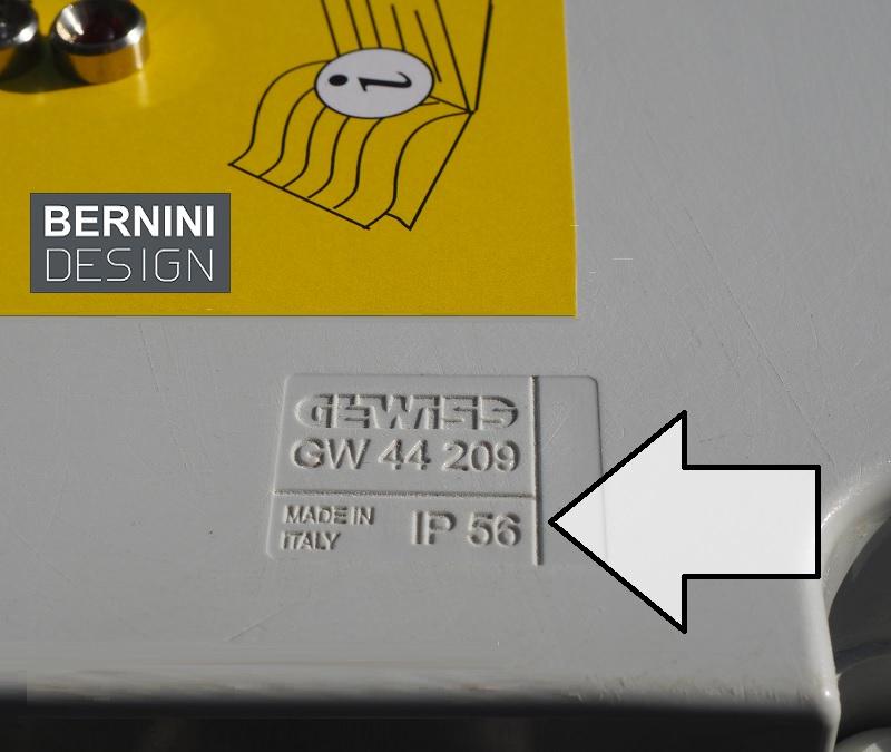
IP56-RATED PLASTIC ENCLOSURE
The box is made of polycarbonate offering IP56 protection. The protection cover is made in LEXAN and features a 3M 467 high-performance adhesive. This guarantees an expected life of over 25 years.
MODEM AUTOMATIC SETUP
Once you send the configuration SMS, the internal Be148-1 gateway will automatically run the installation. The entire procedure lasts about 60 seconds. During this time, the yellow indicator SYSTEM SETUP turns on.

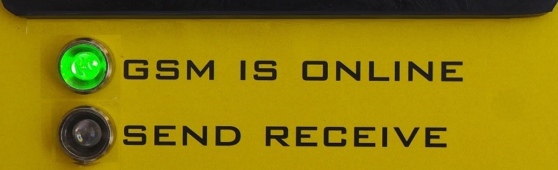
MODEM IS ONLINE WITH GSM NETWORK
After a successful setup procedure, the GSM IS ONLINE green light turns on.
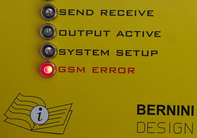
GSM CONNECTION FAILURE
In case of a GSM issue, failure of the antenna, or SIM card, the Be1-GSM panels turn on a red alarm light.
INDICATION OF INCOMING OR TRANSMITTING SMS
When the Be1-GSM panel detects a valid SMS, the yellow indicator SEND RECEIVE turns on for a second.

GSM REMOTE START-STOP
The main output of the Be1-GSM panel is the FUEL SOLENOID. This can be used to start the engine or supply external equipment able to start the generator. The [OUTPUT ACTIVE] green indicator that the Be1-GSM panel instructs the engine to start and stay running until a STOP command is detected.

ENGINE INSTRUMENTS
According to the settings made on Be1, the panel will send all information gathered about analogue measurements of temperature, oil pressure and fuel level.
SUITABLE FOR GAS, GASOLINE OR DIESEL ENGINE
Thanks to the flexibility of the Be1 generator controller you may connect any style of engine. Be1 features adjustable settings for pre-glow and gas-purge solenoid.
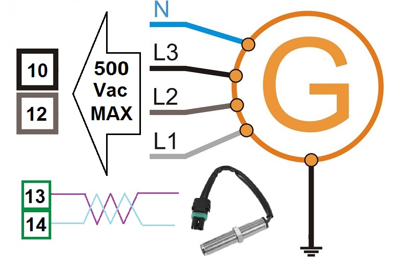
ENGINE AND GENERATOR MONITORING
The Be1 is capable of monitoring generators up to 500V. It can measure the frequency of the alternating voltage but you can add a pickup in case you have machinery without the alternator.
AUTOMATIC FUEL LEVEL SMS NOTIFICATION
To get real-time measurements via SMSB, you must connect a Fuel Level Sensor. You will get an automatic notification every 10% change in the fuel level.
AUTOMATIC START SCHEDULER
Be1 can periodically automatically start the engine based on your settings. For example, you can set to start the engine every 10 days for 5 minutes. The engine will automatically stop following your settings.
LOW BATTERY AUTOMATIC START
You must watch the battery when a generator is placed in a remote place. You can set up an automatic start based on low battery voltage. The engine will only stop when the battery voltage rises above a particular setting or after a programmed delay time.
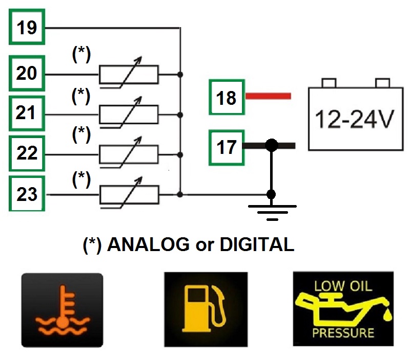
REMOTE DIGITAL INPUT
The Be1 controller features a default setting for [INPUT 4] with the option [12]. This is a REMOTE START feature. This input is also connected to the JD3-4 Be148-1 outputs. In other words, the Be1 receives all requests for a remote start on this input. When you connect terminal #23 to the battery minus, the Be1 will start the engine (hardware REMOTE START input). You can connect here, in logic 'OR' fashion, start requests coming from the pressure switch, level switch, and a relay suitable for your application. You can set up a delay to start and a delay to stop the engine in seconds or minutes.
ENGINE INPUT CONNECTIONS
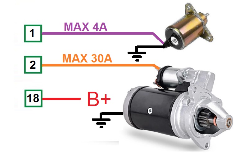
ENGINE FUEL SOLENOID AND STARTER CONNECTIONS
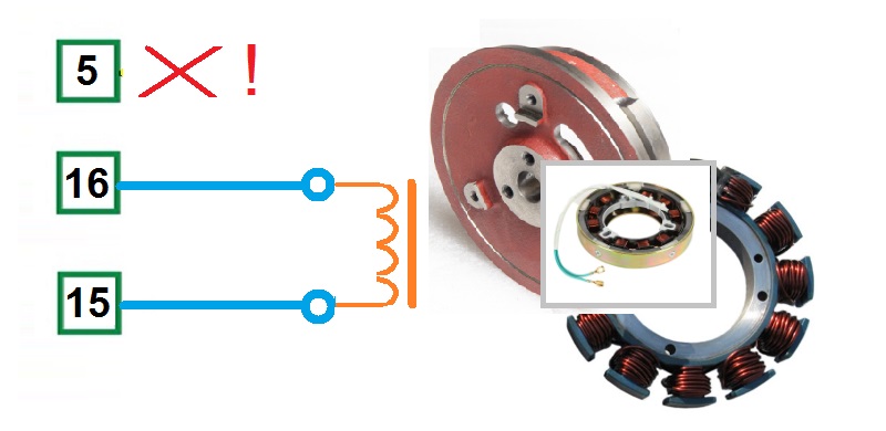
FLYWHEEL GENERATOR CONNECTION
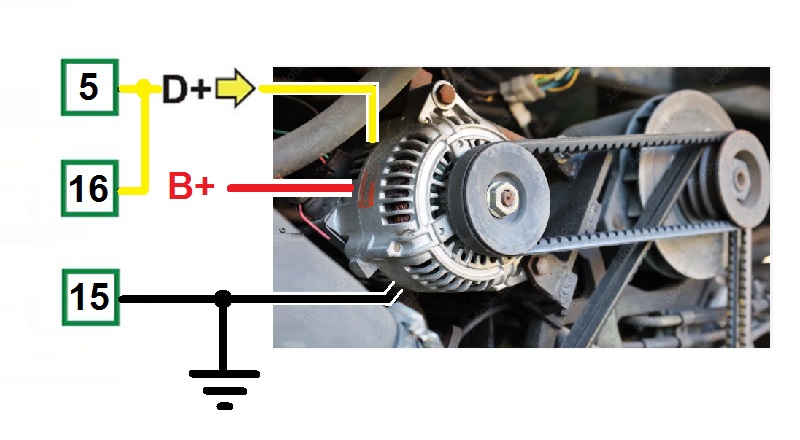
BELT ALTERNATOR CONNECTION
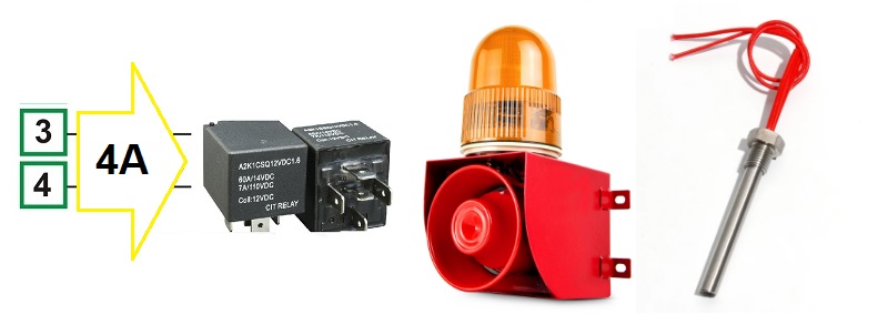
GENERAL PURPOSE OUTPUTS
ALTERNATOR AND OPTIONAL PICKUP CONNECTIONS
PURCHASE THE BE1 GSM-BASED GENERATOR CONTROL PANEL
FREE SHIPPING TO THE EU-US-CANADA
DELIVERY TIME 20 DAYS
3-YEAR WARRANTY
549€
Before making a purchase you can contact us at 0039 335 70 77 148 or mail us at [email protected]. You can pay using a bank transfer after receiving the details for issuing the proforma invoice.
ONLY PURCHASE BE1 GSM KIT
GSM GENERATOR CONTROL PANEL INSTRUCTION MANUAL
FREE SHIPPING TO THE EU-US-CANADA
3-YEAR WARRANTY
DELIVERY TIME 10 DAYS
349€
If you want to make your panel, we offer you the kit of components:
-THE BE148-1 SMS GATEWAY (RAIL MOUNT)
-F1403 MODEM WITH CABLES AND ANTENNA
-THE BE1 GENERATOR CONTROLLER
-RS485 CABLE
-BE148-1 PRINTED INSTALLATION MANUAL IN ENGLISH
-BE1 PRINTED INSTALLATION MANUAL IN ENGLISH
Before making a purchase you can contact us at 0039 335 70 77 148 or mail us at [email protected]. You can pay using a bank transfer after receiving the details for issuing the proforma invoice.
GSM PANEL INSTALLATION GUIDE
This guide helps you understand the required steps to make the GSM panel work. You will find detailed information on the following
[1] Find a proper place for the panel in proximity to the generator. A reasonable distance will be 10 meters. If there is no GSM field, you can optionally place the GSM gateway as far as 1000 meters. The module communicates with Be1 via an RS485 serial interface that supports the MODBUS-RTU protocol. Contact us, to get additional information.
[2] Insert the SIM into the modem. Make sure the SIM has the PIN disabled. If not, you must disable it by using a mobile phone. You may extend the antenna to a suitable place around the GSM panel.
[3] Make the connections to the generator as indicated in the Be1 installation manual.
[4] When you connect the DC supply, the panel will turn on all LED indicators for a second. After that, the SYSTEM SETUP illuminates to indicate the modem initialization sequence. If the red indicator GSM ERROR blinks, the power supply is lower than 8Vdc and you must increase the supply above 10Vdc.
[5] You can observe the modem status by looking at its three LED indicators. The green indicators ‘Power’ and ‘Online’ will turn on. The green indicator ‘Act’ will blink from time to time. The green LED indicator ‘Online’ will blink slowly when the modem is connected to the GSM network. This will take approximately one or two minutes.
[6] When the modem is active, the green GSM IS ONLINE indicator turns on. At the same time, the SYSTEM SETUP indicator will turn OFF. If the red indicator GSM ERROR is permanently on, the Be148-1 failed to detect the MODEM.
[7] Carry out a full generator or engine test without GSM. Follow the Be1 controller instruction manual. Set the Be1 in OFF mode.
GSM COMMUNICATION SETUP
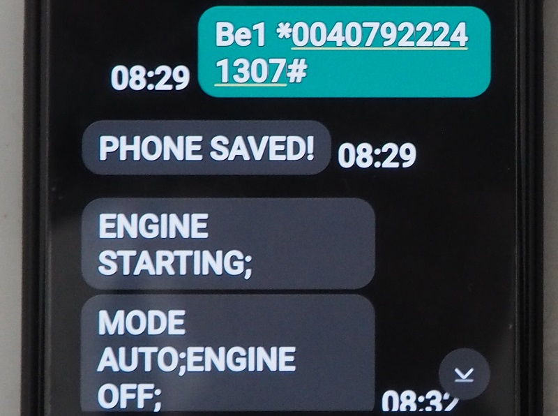
[A] When the green GSM IS ONLINE indicator is on, type on your mobile BE1 *PHONE NUMBER#. Type a blank space after Be1 and before the symbol *. The * is the asterisk symbol. The # is the hash symbol. The PHONE NUMBER is your mobile phone number that must include your country code. The system accepts either lower or upper-case letters. Send the SMS to the modem SIM card. When the Be1 receives or sends an SMS, the SEND RECEIVE turns on for a second.
[B] After a few seconds you will receive the SMS with the text: PHONE SAVED.
[C] Remove the power supply for about 5 seconds, then reconnect the DC power supply.
[D] After 2 minutes you must receive the SMS MODE OFF; ENGINE OFF; NO ALARMS.
Congratulations, the system is ready for use. The next section describes the syntax of the available commands.
USER-FRIENDLY SMS SYNTAX
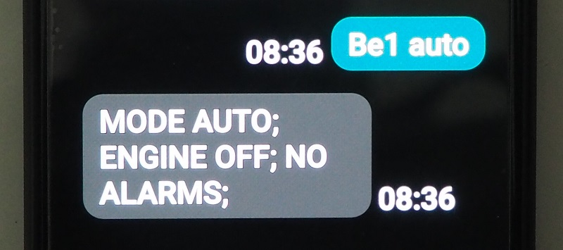
It sends a request to enter the AUTO mode of operation. When the Be1 controller is in MANUAL mode, this command is ignored. The Be1 will acknowledge the command by sending the text [MODE AUTO;]
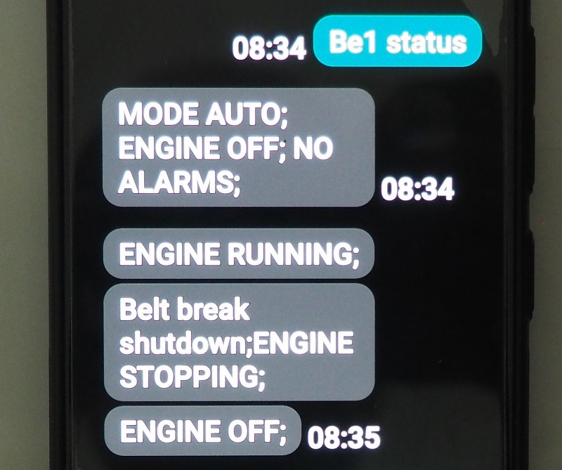
It sends a request to get the engine status, mode of operation and alarm presence. to read. Example of answer [MODE AUTO; ENGINE OFF;NO ALARMS;]
It sends a request to get information about active alarms. The message [NO ALARMS:] is sent if Be1 does not have at least one active alarm.
It sends a request to read the voltage and frequency of the generator. Example of answer [VOLTAGE(V)=230; FREQUENCY(H)=50.4;]
It requests to read Battery Voltage, Speed, and all engine instruments enabled on the Be1 controller. Example of answer [BATTERY(V)=12.4; SPEED(RPM)=1550; OIL(BAR)=4.8; FUEL(%)=76; HOURS=2765;]. The display will not indicate measurements about disabled sensors.
It commands the BE1 to shut down the engine by entering the OFF mode. This command works if the Be1 controller is in AUTO mode of operation (it does not work in MANUAL mode). The Be16-1 will return the message [MODE OFF;].
It requests to read Battery Voltage, Speed, and all engine instruments enabled on the Be1 controller. Example of answer [BATTERY(V)=12.4; SPEED(RPM)=1550; OIL(BAR)=4.8; FUEL(%)=76; HOURS=2765;].The display will not indicate measurements about disabled sensors.
Commands the BE1 to shut down the engine by entering the OFF mode. This command works if the Be1 controller is in AUTO mode of operation (it does not work in MANUAL mode). The Be16-1 will return the message [MODE OFF;].
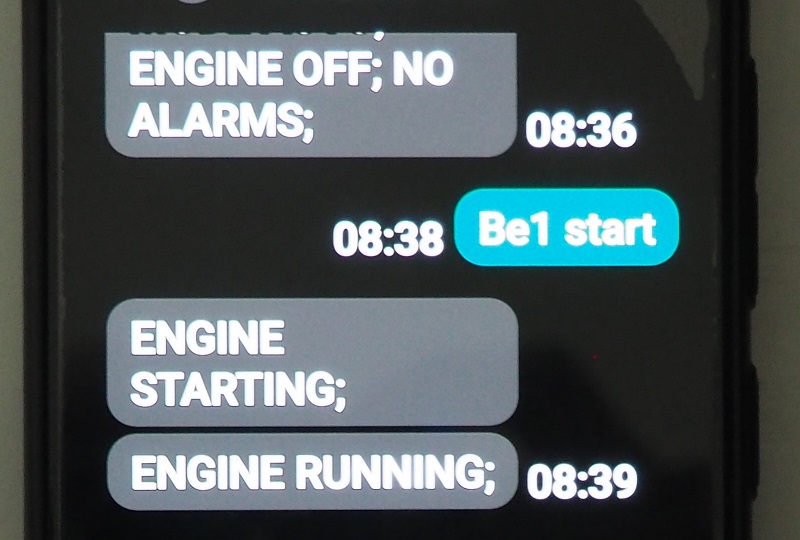
It makes starting the engine (only if Be1 is in AUTO mode of operation). The Be16-1 will return the message [ENGINE STARTING;]. If the engine fails to start you will get the descriptive SMS [Fail to start shutdown;][ENGINE OFF;]. When the engine starts you will receive the SMS [ENGINE RUNNING;].
After you start the engine using an SMS, this command stops the engine. As an option, you can type the SMS [be1 off]. In this case, you stop the engine and instruct the Be1 controller to enter the OFF mode.
BERNINI DESIGN SRL
Zona Industriale
46035
Ostiglia Italy
+393357077148