What Is a Generator Controller?
A state-of-the-art generator controller integrates one electronic module, an engine control unit, a charging alternator monitoring module, and programmable relays committed to protecting all systems of the diesel power generator.
CLICK THE IMAGE FOR HD. The Be124 CENTURION generator controller does much more. To get the most from it, browse this page and discover the extraordinary features of this generator controller.
LOOKING FOR A GENERATOR CONTROL PANEL?
GENERATOR CONTROL PANEL TUTORIAL
By installing the Be124 CENTURION generator controller, you can make an extraordinary generator control panel suitable for industrial applications, telecom or 400Hz GPU (Ground Power Unit for the aviation sector)
CLICK THE IMAGE FOR HD

Thanks to the embedded Canbus and Modbus, you can integrate your diesel generator in the factory automation system. At the same time you can make a user-friendly generator control panel with the essential components.
BE124 GENERATOR CONTROLLER PRICE
199€
FREE SHIPPING WORLDWIDE
GET REAL-TIME OEM PRICE. ASK FOR A CUSTOMIZED VERSION
We can offer an extraordinarily interesting offer if you directly purchase from our European factory. The basic price is ex-wrks, but we can offer free-shipping solutions as well thank yo out worldwice contact with FEDEX and DHL. Standar order batchhes are 10, 25, 50 ad 100 pieces.
GENERATOR CONTROLLER PRICE FOR OEM
OSCILLOSCOPE & DATA LOGGER
The advanced Be124 generator controller includes a DATA logger, a real-time oscilloscope, a real-time clock, CAN-bus and MOD-bus interface, and at least 150 adjustable settings offering GSM connectivity for remote control and monitoring.
THE BE124 UNBELIEVABLE FEATURES
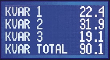
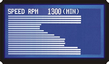
The Be124 is the most powerful generator controller on the market. It features extremely accurate measurements for Vac - Aac - Hz - PF - Vac - Vdc - RPM - kW - kVA - kVAr - kWh - PF- BAR - PSI - °C - °F.
THE OSCILLOSCOPE
You can put on screen the shape of the waveform about voltages and current especially when your generator is working around its limits.
CLICK THE IMAGE FOR HD
KEY+AUTO START
Feel comfortable starting your generator in the same way you start your car. In addition to it, once you push the AUTO button, you can benefit from a multisource AUTO start generator module.
THE LOW BATTERY START
Especially when your generator is placed in a remote location, without mains, you need to set up an automatic start to keep the battery healthy. Again, this is simple with Be124 by setting a limit for low battery start and a limit for high battery stop. You can set up a time-out.
THE CANBUS J1939
The Be124 interfaces with ECUs compatible with the J1939 protocol. The Be124 generator controller can remotely start the engine providing real-time control and monitoring of all engine instruments.
THE MODBUS MONITORING
First, we provide a full map of the MODBUS registers. You can develop your remote control monitoring using the MODBUS communication protocol. The Be124 can directly drive up to 1000 meters of twisted cable. You can connect up to 24 generators on the same communication cable. Second, we offer software for remote control monitoring free of charge.
THE ENGINE INSTRUMENTS
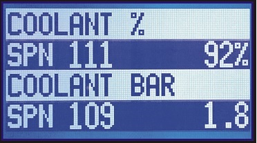
The Be124 features analogue configurable inputs. What's more, you can connect transducers with the scope of monitoring important parameters of the engine like oil pressure, temperature and fuel level,
THE TRANSIENT RECORDER
Using the embedded transient recorder you can analyze the key parameters of your generator like battery voltage during crank sequences, speed variation when you connect a load, oil pressure variation, charging alternator voltage and many others. Next, you can set up an automatic start-stop of the data transient recorder.
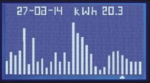
THE 16 CHANNEL DATA LOGGER
The Be124 can record and store up to 16 channels of measurements including an energy counter.
UNIVERSAL 50-400Hz
Does not matter if it is for industrial, commercial, or avionic applications. The Be124 powerful CPU can calculate TRMs up to 600Hz. You can safely use the Be125 in a GPU application (Ground Power Unit Generator).
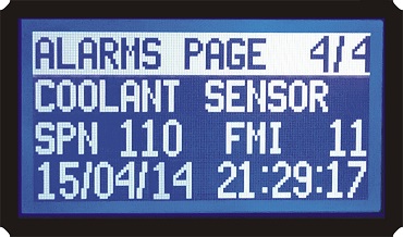
THE 200 LOG-EVENTS RECORDER
For a remote location, it is mandatory to store the main events. The Be124 has 3 non-volatile memory areas. This will allow you an extremely reliable way to record data. You can access this area of memory via TCP/IP or GSM.
WEEKLY/DAILY SCHEDULER
Using the Be124 generator controller it is easy to schedule time slots of the day to disable the generator start. In the same way, you can create a slot of time in which you start the generator to suit particular needs.
ITS COMPACT SIZE
Today, no one can create a generator controller that is so small and fits inside a typical 96x96 DIN size.

INSTALLATION MANUAL
You can use the Be124 for industrial diesel-driven heavy machinery. This generator controller works up to 600Hz. In other words, it is a suitable choice for aircraft ground support equipment generators. You can connect the Be124 to TCP-IP or GSM systems. The Be124 generator controller is the appropriate solution when you have to refurbish the GAS-GASOLINE-DIESEL generator. In effect, it can monitor generators up to 1000kVA. In addition to standard configurable input & output, the Be124 complies with SAE J1939 via a fully isolated CANbus interface. In conclusion, the BE124 is the best option as long as you have to control a highly valuable generator.
WHAT IS THE PURPOSE OF A GENERATOR CONTROLLER?
The main purpose is to add remote control, protection and monitoring. This is of vital importance when it comes to solar systems. The generating set is always in a remote location. It must be able to start when battery storage is low. The generator control unit will directly send all information via GSM, MODBUS or TCP/IP. For the Be124 generator controller, the above tasks take only 25% of the CPU.
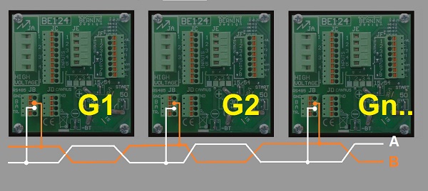
In the above image the Be124 CENTURION generator controller combined with an industrial-grade MODBUS-UBS gateway. You can install up to 128 generators in an RS485 network. Each generator will be associated with a 'node'. The software can manage 127 nodes. By maintaining a baud rate at 19200 bps you can use a twisted pair as long as 1000m. Each RS485 module is an intelligent repeater. You can theoretically make a chain of 127 kilometres without losing digital information and accuracy.
WHAT IS THE PURPOSE OF GENERATOR PLC?
The Be124 CENTURION generator controller is a generator Programmable Logic Controller. It features over 200 programmable functions. By changing the settings you can modify the logical functions of control and protection. You can adjust the parameters on-site via keyboard or remotely via MODBUS. The parameters are stored in a multi-level non-volatile memory. The data are automatically and continuously verified. If there is any corruption in the data, a warning will be generated.

In the above image the TCP/IP server with an encrypted HTTPS server.
DIESEL GENERATOR MONITORING SYSTEMS
GENERATOR CONTROLLER WIRING DIAGRAM
CLICK THE IMAGE FOR HD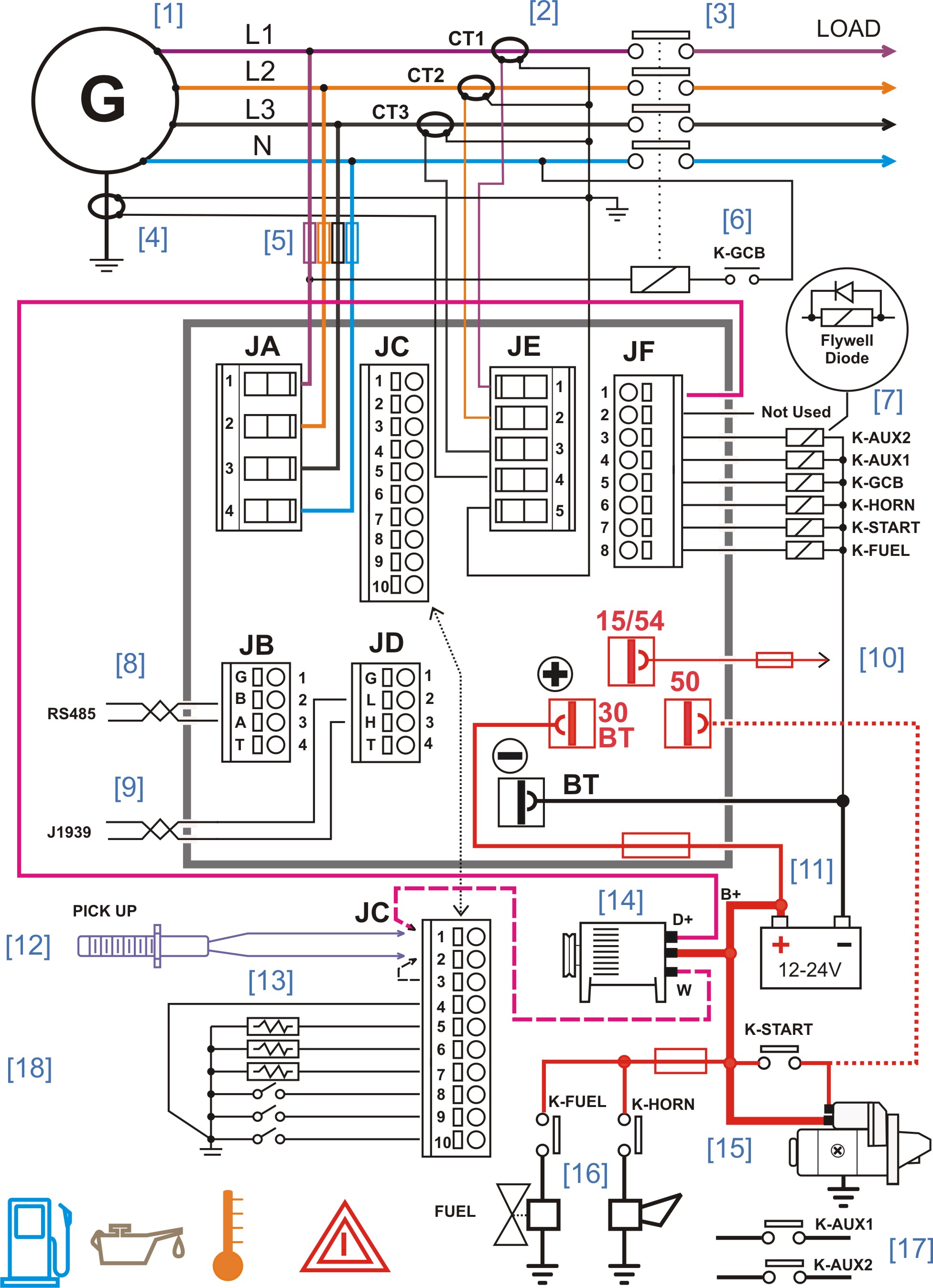
By following or generator control panelwiring, you may build a cost-effective generator control panel. You can use this wiring diagram to control any kind of engine and generator. By settings the parameters in a suitable way, you can use a simplified wiring diagram for a single-phase generator.
READ MORE ABOUT GENERATOR CONTROL PANEL WIRING
GENERATOR CONNECTIONS OVERVIEW
[1] GENERATOR VOLTAGE. [2] ANALOG & DIGITAL INPUTS. [3] RS485 MODBUS PROTOCOL. [4] CANBUS SAE J1939. [5] BATTERY SUPPLY [6] BATTERY PLUS. [7] STARTER PILOT [8] DASHBOARD SUPPLY. [9] DIGITAL OUTPUTS.
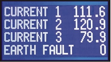
The generator is connected to the input voltage sensing circuit via fuses (5). Current Transformers (2) must be provided to protect the generator from overload problems. We recommend that you also connect an EARTH-FAULT TRANSFORMER (4). The circuit breaker should be operated via an ON/OFF coil [6]. In case of trouble, the Be124 protection relay will disable the circuit breaker protecting the LOAD and the Generator.
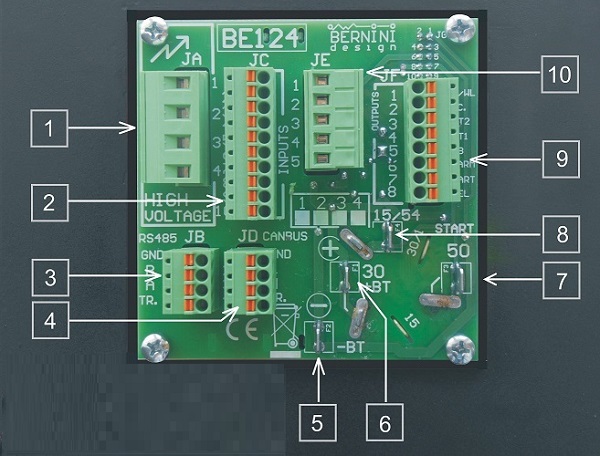
BE124 CENTURION GENERATOR CONTROLLER INSTALLATION MANUAL
Removable connector JF allows you to connect all output relays with pre-configured or user-programmable options. The front panel features a Key switch (10). It can be mainly used to start the engine with a manually operated generator. The best-recommended option is to use the JF-7 (start-output) which will allow you safe MANUAL and AUTOMATIC operations. As long as you need remote monitoring using a computer, the Be124 coupled with its RS485 port supports the MODBUS-RTU protocol. In case your engine is controlled by an ECU (SAE J1939), the Be124 provides the CANbus isolated port. You can connect any SAE-J1939 compatible engine. To summarize, the Be124 Centurion features a fully configurable PICKUP input. It will be able to provide rotational speed information and a proper crank setting. As a result, you will have at your disposal a powerful monitoring tool.
HOW TO GET THE MOST FROM A GENERATOR CONTROLLER?
A generator controller is a complex piece of technology. It integrates circuits working at low voltage and high voltages. As a result, we can say that a generator controller monitors the parameters of the Engine (Oil pressure, Temperature, Fuel, Speed, and others), the Charger Alternator, and the main Alternator. The software compares the settings of the alarms stored in the memory with the measurements made on the input circuits. The main task is using the result of these comparisons to generate alarms, protecting actions, warnings, or logic functions (it activates a particular output for example). A high-tech generator controller must feature a range of programmable settings and be engineered to comply with international standards like NFPA110 CSA. If the CANBUS is not available, a good Generator controller must be capable of interfacing with analogue sensors or switches for the OIL/°C/FUEL/Auxiliary Temperature monitoring. Equally important, for a generator controller, is the ability to operate reliably in a range of environments, from minus 25 up to 70 degrees Celsius. Even if the design of a generator controller complies with international standards, a bad layout of your application may deteriorate the reliability of your generator controller. Here there are you why.
WHY A GENERATOR CONTROLLER MUST NOT MONITOR THE UTILITY POWER?
The reason is simple: independently of the "ACCEPTABLE COST" measures that you can take to prevent flashes of lightning or over-voltages from hitting your electronic equipment, you will never be safe enough. IT IS NOT ABOUT INSULATION. The over-voltage transients are coupled to electronic components via capacitors.
NEVER LIKE THIS
AVOID DIRECTLY USING AMF CONTROLLER ON YOUR GENERATOR
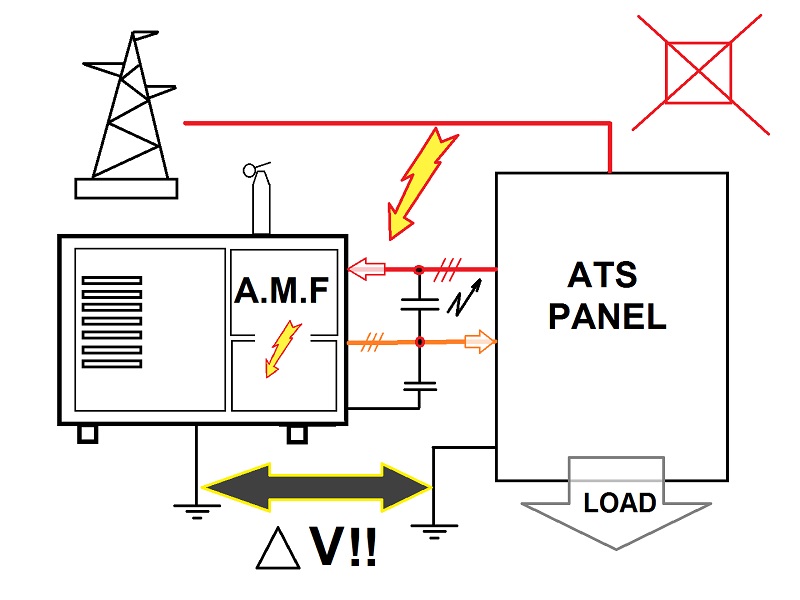
You will never be able to reduce the capacitance to 0 pF; NEVER! The best choice is always to make an automatic mains failure panel or an automatic transfer switch panel and remotely drive the auto-start remote input of your generator controller.
THIS IS THE WAY TO DO IT
ALWAYS TRUST IN A GOOD AUTO-START CONNECTED TO AN EXTERNAL PANEL VIA INSULATING RELAY
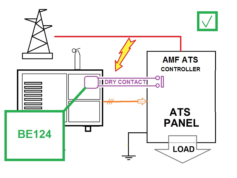
The overvoltages will not affect the power generator or the generator controller. There is no coupling from parasitic capacitors and no direct cables from utility power. You can start the engine and use the generator even if the ATS controller is damaged.
BE124 SPECIFICATIONS
Generator Controller Cranking Dropout: 0V for a half-second (initial voltage: 12Vdc).
Weight: 550 grams.
General design: ECC 89/336, 89/392, 73/23, 93/68, IEC 68-2-6. Certification: CE
Generator Voltage: nominal voltage 70 Vac up to 600Vac (Ph-Ph) 347Vac (Ph-N). Overvoltage: 4KVac Ph-Ph.
Voltage Measurement precision (V/Hz): +/- 1% F.S.. Impedance: 2 M Ohm. Resolution: 1Vac.
Generator Controller Frequency: nominal frequency 20.0 Hz up to 600.0 Hz. Measurement precision: +/- 1% F.S.
Measurement Circuit Impedance: 2 M Ohm. Resolution / Accuracy: 0,1Hz (20.0-600.0Hz).
Current Sensing: 5/5Aac up to 2000/5Aac. Maximum permanent current on the sensing inputs: 7Aac.
Current Measurement precision: +/- 2%. Internal resistance: 0.05 Ohm. Resolution 0,1Aac (<500/5), 1Aac (>500/5).
Digital Inputs: open circuit voltage of approximately 4,5V - Trigger level: < 2Vdc (max 5mA).
Maximum Overvoltage: +/-100V 1 s. Permanent short circuit to Bt+ and Bt- allowed for unlimited time.
Analog Inputs: resistance range 0 up to 1000Ohm. Current at zero Ohm: 5mA. Overvoltage +/-100V. Accuracy: 2%.
Supply Surge: 100Vdc /500 Amps (8/20 microseconds). Absorption capacity: 8 Joule max.
Dimensions: 96mm X 96mm X 87,5mm. Panel Cut-out: 91mm X 91mm, outdoor operation.
Operating Temperature Range: -25 deg. C up to +70 deg. C. Humidity Range: 5% up to 95% non-condensing.
Generator Controller Static Outputs: positive logic / 150mA output current / short circuit proof.
Charger Alternator Monitoring: operating voltage up to 36Vdc/3W. Vdc readingaccuracy +/- 2%.
Magnetic Pickup Input: 0,5V-50VRMS, 10-25KHz. RPM reading accuracy +/- 1%. Teeth Count: 10.0/500.0.
CAN Port: fully isolated. 250Kb/second. Internal 120 Ohm impedance available for connection. Supports the SAE1939 protocol.
RS485 Port: supports Modbus Protocol and drives 1000 Metres of twisted cable, ESD 2KV & drives up to 127 nodes.
THE USER-FRIENDLY INTERFACE
[1] DISPLAY [2] WARNING [3] LOW FUEL [4] KEY START [5] ALARM RESET [6] OIL PRESSURE [7] ENGINE TEMPERATURE
[8] AUTO BUTTON [9] GCB BUTTON [10] SHUTDOWN ALARM [ 11] RIGHT ARROW [12] DOWN ARROW [13] UP ARROW [14] LEFT ARROW
USING THE GENERATOR CONTROLLER
The mode of operation of Be124 is selected via a key switch and a [AUTO] push button. If the Be124 generator controller was in TEST or AUTO mode before power down, when you switch on the battery supply, the Be124 generator controller automatically enters the AUTO mode of operation. In other cases, you have to manually start the engine.
OFF MODE
Turn the key to ‘OFF’: you switch OFF the Be124 and clear the fault alarms. You are allowed to program the parameters or modify the settings. The backlight of the display will shut down automatically after a 30-minute timeout. To exit the OFF mode turn the key to ‘ON’.
MANUAL MODE
Turn the key to the ‘ON’ position. After the automatic 5-second self-check turn the key to the ‘START’ position until the engine starts. The display will automatically show the ‘Be124 Status’ page. During cranking, depending on the efficiency of the battery, the generator controller may turn off the backlight of the display.
Wait until the green LED GCB-ON starts blinking-
This means that the generator is working within the settings. Push the [GCB] push button to close the generator circuit breaker: the green LED [GCB] will light and remain lit. Use the arrow buttons to browse the instrumentation. Push [ACK] at any time to open the ‘Be124 Status’ page. Push the [GCB] pushbutton to open the generator circuit breaker. To stop the engine, turn the key to the ‘OFF’ position; the messages [MODE OFF] & [STOPPING] will appear on the display for the programmed 'Stop Solenoid' time. After a complete stop, you can restart the engine.
AUTO MODE
Turn the key to the ‘ON’ position. Push the [AUTO] push button until the yellow LED [AUTO] illuminates. The engine starts when the generator controller detects a request to start from a configurable input. The green LED GCB blinks when the generator is working within the programmed limits. After the [WARM UP] time, the generator circuit breaker (GCB) will close automatically.
Use the arrows to browse the instrumentation
Push [ACK] at any time to display the ‘Be124 Status’ page. When there is a request to stop the engine, the generator controller opens the GCB and triggers the [COOL DOWN] time. After that, the Be124 will stop the engine. In the auto mode of operation, the generator controller will periodically test the engine if the scheduler is correctly programmed. During the test, the yellow LED [AUTO] will continue to blink; the display indicates the message [TEST]. To stop the engine, turn the key to the ‘OFF’ position at any time. The display continuously informs you about what Be124 is doing. The engine will start when you program the AUTO START function as well.
LOW-BATTERY AUTO-START
You can set up a low battery limit, high battery limit, delays and a time-out. When the controller is in the AUTO mode of operation, the Be124 continuously monitors the battery voltage. If the voltage drops below the setting for about the time you previously defined, the Be124 will start the engine. Once the battery is supposed to be fully charged, the Be124 will stop the engine. In case the battery will not be able to reach the high battery setpoint, the timeout alarm stops the engine and triggers the battery alarm.
REMOTE START
The Be124 manages multiple sources of remote start. It could be from a programmable input, let's say a hardware start request or a software start request from MODBUS or TCP/IP. You can set delays to start and stop and timeout protection as well.
SCHEDULED START
The Be124 Scheduled Start menu allows you to set the day and time of the week when the automatic start is scheduled to begin. On the same menu, you will set the time to stop the engine. You can make only a scheduled start par day. You can set up a different start-stop cycle every day. The Be124 will repeat the same cycle every week supposing you keep the generator controller in AUTO mode of operation.
TEST MODE
Turn the key to the ‘ON’ position. Hold the [AUTO] push button for at least 10 seconds until the display indicates the message [TEST MODE] and the yellow LED AUTO starts blinking. The generator controller will start the engine immediately. The generator controller will enable the generator circuit breaker (GCB) only if not otherwise programmed by the parameter [GCB TEST CONTROL]. To exit the ‘TEST’ mode, push the [AUTO] push button: the generator controller will enter the ‘MAN’ mode of operation.
ABOUT A GENERATOR CONTROLLER SAFETY
The purpose of this web page is to help you optimise the use of our products, a generator controller, an electric panel, various accessories, and a simple automatic battery charger. You can directly find the information you need in PDF form. We vividly recommend that you follow the indications and application wiring diagrams included in the OEM manual of the product that you are going to use. You can download the OEM manual using the links closer to the product description on each web page of this website.
PLEASE NOTE
a) The improper wiring of a generator controller could damage your Engine, Generating Set, Panel, or equipment fitted with a Bernini Design controller (generator controller, generator control system, generator control unit, or generator control module).
b) The improper wiring or improper arrangement of our generator controller could also be dangerous for people working with the equipment that you are going to build (generator, power generator, or similar equipment driven by an engine).
c) Bernini Design is not responsible for the installation or operation of any generator controller, diesel generator set, generator panel, or equivalent equipment fitted with a Bernini Design controller.
d) If there is any doubt about the use of a generator controller (or equipment) controlled by a Bernini Design controller, you must contact the company responsible for the installation or the manufacturer of the machine (power generator, compressor, pump set, and so on).
DO NOT FORGET
A) Installing a Bernini Design generator controller implies working with dangerous currents and voltages. You are required to install fuses or equivalent devices to limit the amount of the current especially when you connect or wire batteries.
B) The installation must be carried out by qualified personnel only (qualified electrical technicians).
C) Disconnect all Electrical Power sources (Mains, batteries, and others) and make sure the engine (or equipment) is inoperative before commencing the installation of a generator controller.
D) Any modification to a Bernini Design controller or any use beyond the specifications provided by Bernini Design, may cause personal injury, damages to equipment, or injury to living beings.
E) Ensure that Mains Power (or public network supply) is isolated. Connect the equipment only after observing the correct rated voltage & current.
F) All the time consider the risk of explosive gases working closer to LEAD ACID BATTERIES.
BERNINI DESIGN GENERATOR CONTROLLERS LIFE SUPPORT POLICY
Bernini Design SRL Generator Controller manufacturers declare that the Bernini Design products are not authorized for use as critical components in life support systems. A life support systems are intended to sustain life, and whose failure to perform, can be reasonably expected to result in a significant injury or death of the living being, human or animal.
BERNINI DESIGN SRL ITALY
46035 Ostiglia Italy
INDUSTRIAL PARK
bernini@bernini-design.com
Support
+39 335 7077148