
ATS Circuit Diagram
The ATS circuit diagram is suitable for driving a contactor-based or a motorised changeover.
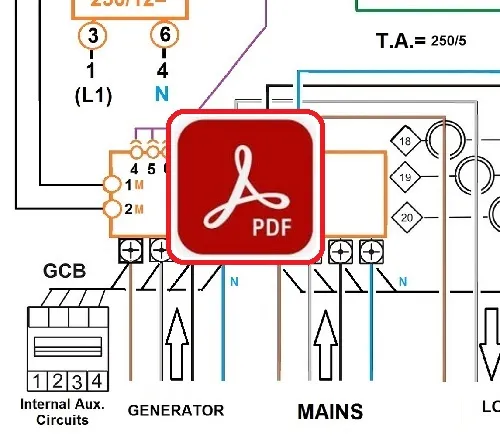
A Bernini Design ATS controller is engineered to provide reliable power management between a primary mains utility source and an emergency backup diesel generator. The paired interface relay board can connect all kinds of engines. In other words, the best option when you want to refurbish a second-hand generator. The following PDF file is a useful tooll that explains all details about contactors and motorised switches.
Download ATS Circuit Diagram PDF (4,90)
Core Wiring Diagram Design Philosophy
The Be242 controller gives absolute priority to the utility power source in case the controller is damaged or lacks an auxiliary supply. Users are protected from unexpected power failures as long as utility power remains healthy. You can make your own ATS control panel today. Purchase the:
How to build ATS Panels: 9.90€ e-book
This e-bbok shows step-by-step how to build a 40 KVA electric panel suuitable for a standby generator.
3-Phase Contactor-Based Changeover ATS Circuit Diagram
The contactor-based changeover consists of two 4-pole, mechanically and electrically interlocked contactors. The proper "technical" term for this kind of panel is "AMF Panel". Controllers like Be242 and BeK3 have the capability of running ATS and AMF software simultaneously in real time. You can read more about this topic in the following free tutorial:
Lean how to make a contactor interlock circuit
The PDF wiring exaplains all details oh how to make a safe electrical interlock for a professional changeover.
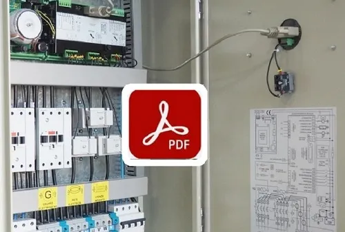
Single-Phase Contactor-Based Changeover ATS Diagram
A smart way to make a single-phase ATS panel is by using the basis of a 3-phase wiring diagram configuration. The simple trick is to parallel the contacts as indicated in the "ATS Wiring Diagram PDF". You are required to use single-phase circuit breakers [MCB] and [GCB] in a way to protect the internal wiring in case of a short circuit. You may use a single C.T. of a suitable size.The Be242, in this case, must be configured to single-phase by programming the appropriate setting. The Be242 ATS controller will only monitor one phase of the mains and one phase of the generator. By paralleling the contactor contacts, you will increase 50% the AC1 current rating. If you use, for example, a 63 A AC1 nominal current contactor, the resulting AC1 current will be around 90 A.
Motorised Switch-Based ATS Circuit Diagram
The motorised changeover consists of a robust switch with three distinct positions: PRIMARY SOURCE, OFF, and SECONDARY SOURCE.
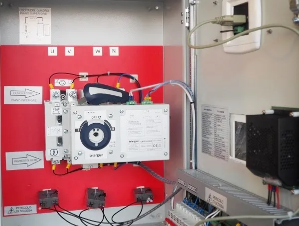
Motorised ATS Panel Benefits Overview:
High Current Capacity: Manages high current demands far exceeding standard contactor limits.
Zero Holding Power: Does not require continuous electrical power to maintain its mechanical position.
Safety & Economy A cost-effective and secure engineering solution for high-power switching applications up to 1000kVA.
The Be242 relay board directly control the status of the motorised switch with only 46wires. Depending on your needs and the kind of motorised transfer switch, you can connect programmable inputs 2 [Input#13], 3 [Input#10] and 4 [Input#14] to proximity switches. This provides a real feedback on the Be242 ATS controller front panel. In other words, it will confirm to the user the position of the switch.
Advanced ATS Wiring Diagram Configuration Examples
The PDF wiring diagram show how easy is to arrange special kinds of configurationi as follow:
Dual Load Systems
Install the ATS controller to supply two separate loads [1] and [2] from a single standby generator. The two loads are totally separated. The generator connects specifically to the load affected by the power outage. This application is highly popular in residential complexes and private multi-property estates, allowing two independent households to resolve power outages with a single shared generator investment.
Dual Genset Systems
The ATS controller supports dual generator configurations as an emergency standby to a single load. A strict BREAK-BEFORE-MAKE configuration is mandatory to protect the load. In prolonged outages, you can configure ENGINE 1 as the master; if starting fails, the secondary engine will automatically engage to supply the load. Both ATS controllers and transfer switches must be housed within the same cabinet.
Bernini Design Srl
Industrial Area, 46035 Ostiglia
Italy
+39 335 70 77 148
bernini@bernini-design.com
WA+40 721 241 361