Auto Mains Failure
The Be142 Auto Mains Failure controller is a "fully-solid-state", NFPA110-Compliant suitable for telecom, military and industrial applications. Over 200.000 Be142 Auto Mains Failure controllers are running worldwide.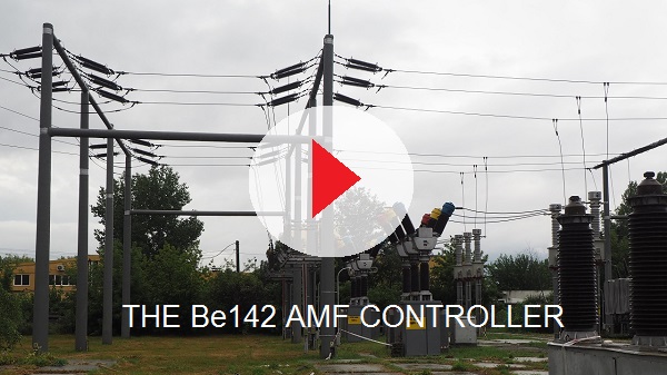
Módulo de control de fallos de red eléctrica automática Be142
Module de contrôle de panne de secteur automatique
Auto Mains Failure Controller Price Breakdown by Quantity
Tiered pricing breakdown ex-works
Eu origin, average delivery time 30 days
Purchase one sample, free-shipping world wide & 10-year extended warranty
329 €
bernini@bernini-design.com
Sales Terms
Qt. |
Unit Price |
Total |
25 |
120 € |
3.000 € |
50 |
99 € |
4.950 € |
100 |
65 € |
6.500 € |
150 |
55 € |
8.250 € |
Auto Mains Failure Tutorial
You can freely browse the page or choose one of the following topics
What is an Auto Mains Failure (AMF) Module?
While the internet is full of redundant explanations, a true industrial AMF module must deliver a clean, robust architecture capable of handling every demanding requirement of a standby generator installation.
The Be142 is a fully re-engineered, milestone AMF controller designed for industrial and telecom applications. It integrates decades of field-proven reliability with state-of-the-art 2026 hardware performance.
Key Architectural & Hardware Highlights
Rugged Display & Build: Features a high-luminosity display for clear visibility across wide climatic conditions, housed in a standard DIN 192x96 horizontal enclosure (weight: 450g).
Industrial-Grade Protection: Analog measurement circuits utilize a proprietary hardware schematic engineered to withstand 4 kV overvoltages.
Flexible Switching: Fully configurable to drive either Contactor-based changeovers (designed to drive two contactors) or Motorized Transfer Switches.
Robust Outputs: Short-circuit-proof outputs capable of directly driving 12V or 24V automotive relays.
Comprehensive Monitoring & Measurements
The Be142 interfaces seamlessly with resistive or digital sensors to provide high-precision monitoring for:
Electrical: Vac, Aac, Vdc, Hz, and multi-phase monitoring.
Engine Metrics: R.p.m., Oil Pressure, Engine Temperature, Battery Vdc, Fuel Level, and Hour Count.
Customization & Connectivity
Over 150 Adjustable Parameters: Safely stored across multiple zones of high-end non-volatile memory.
Industrial Protocols: Built-in RS-485 interface supporting MODBUS.
Remote Management: Optional kits for GSM and TCP/IP monitoring (utilizing our dedicated server for full internet control).
Global Standards: Fully compliant with NFPA-110 and NFPA-99 emergency power system standards.
FEATURES SUMMARY AND INSTALLATION MANUAL
The Be142 is a legendary Auto Mains Failure (AMF) controller that set a new industry benchmark upon its introduction. Now, for 2026, we have completely re-engineered the hardware to achieve unprecedented performance levels.
Robust Engineering & Specifications
Physical Build: 40 terminals, 12 tactile pushbuttons, 13 LED indicators, and a rugged 4-digit military-grade display.
Form Factor & Weight: Compact 2x DIN96 horizontal cut-out dimensions with a robust 450g weight.
Flexibility: Over 100 fully adjustable parameters driven by field-proven, ultra-reliable software.
Built on two decades of market-leading reliability and supercharged with 2026 hardware advancements, the Be142 remains the definitive milestone in AMF control technology.
Buy the Be142 Installation Manual (4,90 €)
Auto Mains Failure Front Panel Features
The front panel is intuitive and user-friendly. A series of ICONS [1] lists the basic alarms. A message alarm is composed of the code [Er] followed by a number. The display [2] indicates all parameters. Five yellow indicators make you understand the menu of the display. Use the buttons F8 and F9 to browse the menus. The button [3] (F10), and the alarm acknowledge function are used for various navigation and programming tasks.
CLICK FOR HD
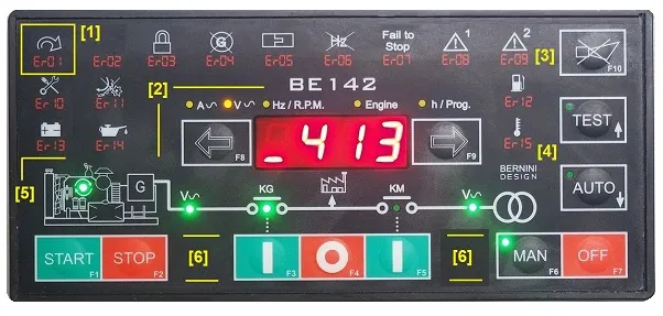
The buttons [4] are used to enter the AUTO or TEST mode. They are also used in programming mode. The area [5] includes all LED indicators about the engine running, the presence of voltage and the status of the contactors. Finally, in the area [6] you find all pushbuttons required to manually control the system and turn the controller OFF.
THE AUTO MAINS FAILURE CONTROLLER REAR VIEW
All connections are made via removable female connectors.
Click the Image to get HD
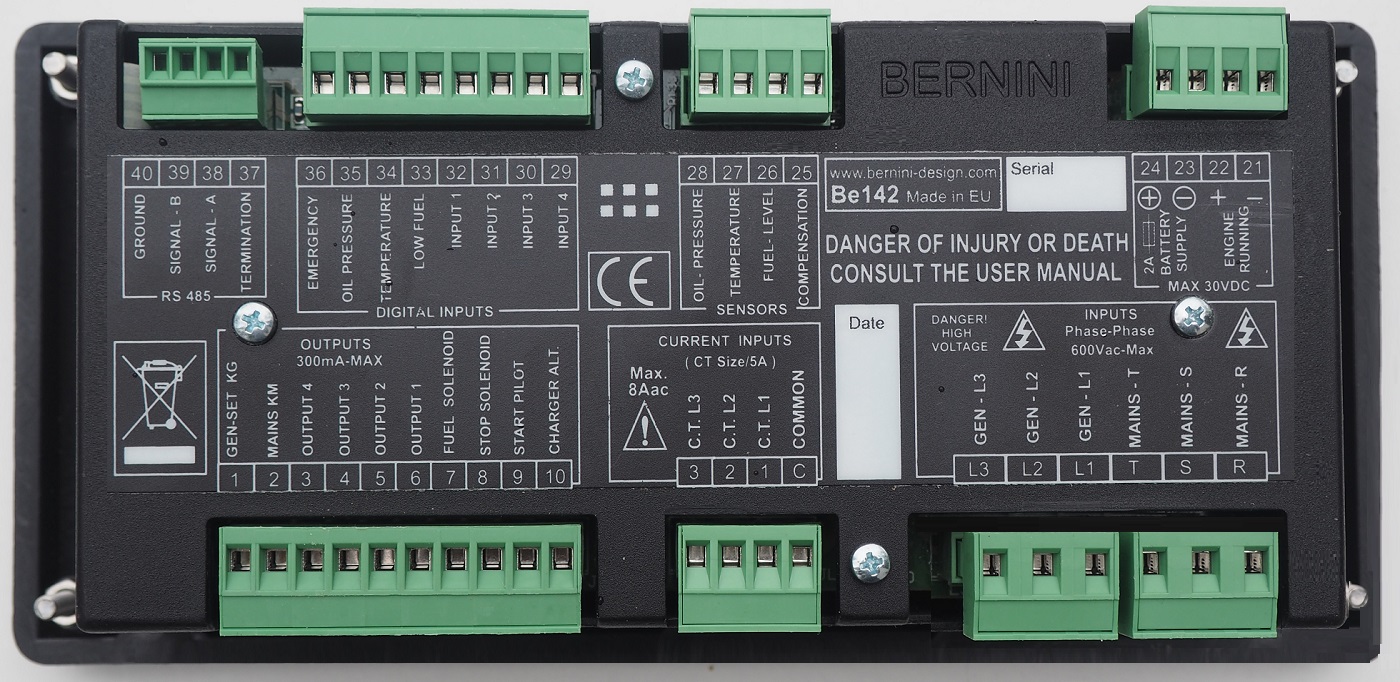
1) RS485 4-POLES PLUG 2) DIGITAL INPUTS 3) ENGINE INSTRUMENTS INPUTS 4) POWER SUPPLY AND ENGINE RUNNING CONNECTIONS 5) GENERAL PURPOSE OUTPUTS 6) CURRENT TRANSFORMERS CONNECTIONS 7) MAINS AND GENERATOR VOLTAGE CONNECTIONS 8) REAR COVER SCREWS 9) 4 X M4 FIXING NUTS
The Be142 shares the same cut-out of a standard DIN 192X96mm enclosure as indicated in the mechanical specifications at the end of the page.
THE AUTO MAINS FAILURE CONTROLLER OUTPUTS
The Be142 features short-circuit-proof static outputs. In addition to the minimum requirements of a typical AMF controller, the Be142 features 4 programmable outputs. Each output can be associated with one of the 61 available options. See Table 7.09 in the instruction manual.
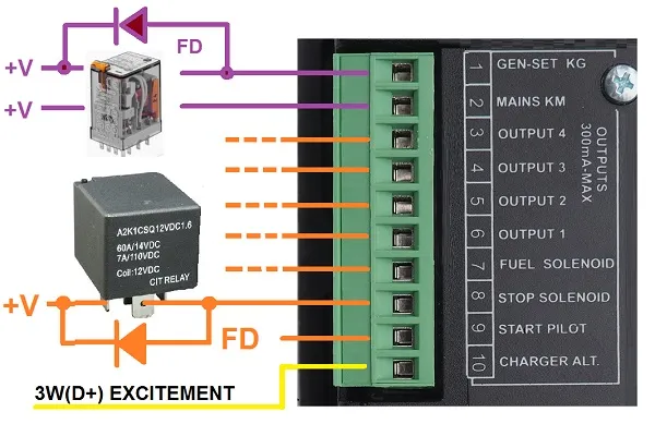
The static output is NPN kind. When an output is active, the output transistor connects the coil of the relay to the battery minus. For this reason, you must connect the other side of the coil to the battery's positive terminal.
WHY USING a FLYWELL DIODE IS SO IMPORTANT
We always recommend connecting flywell diodes to output relays. These diodes prevent arcing and overvoltages because the relay contacts open faster. In other words, diodes are mandatory if you want to make a professional up-to-code system.
THE BE142 AMF CONTROLLER INPUTS
In addition to the minimum input configuration required by a standard AMF controller, the Be142 controller expands the possibilities beyond your imagination.
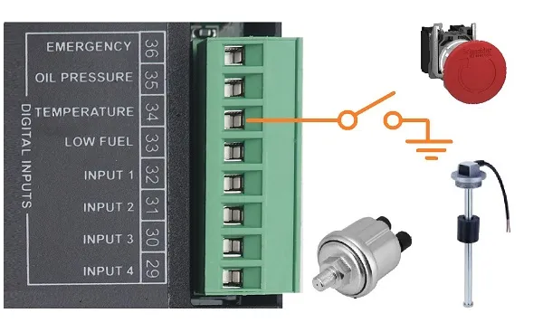
You can choose one of the 28 options available. This allows the Be142 controller to be compared with a PLC controller. You can arrange all kind of configurations like DUAL mutual generator or DUAL load with a single generator. All possibilities are described in the installation manual.
Diving into AMF technology
An AMF controller is an electronic module capable of transferring the LOAD from MAINS to a GENERATOR. In other words, the AMF controller automatically connects the MAINS source first. You can override the automatic control and manually start the generator. The AMF controller is the key component of your AMF panel.
FORGET TOYS WITH LCD
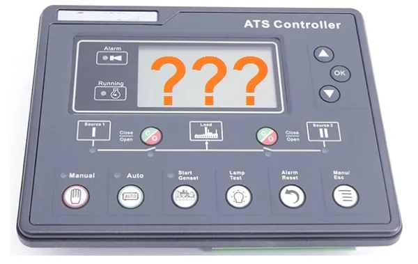
MOVE TO MILITARY-GRADE -30°C/+70°C DISPLAY
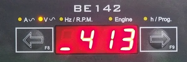
This military-grade display can work at extreme temperatures and last for decades.
Auto Mains Failure Operation
The AUTO mode of operation runs a complex software that guarantees the automatic transfer of the LOAD to MAINS or GENERATOR. In addition to standard timers included in the commonly available models on the market, the Be142 features additional programmable timers to safeguard the contactors, preventing dangerous bounces.
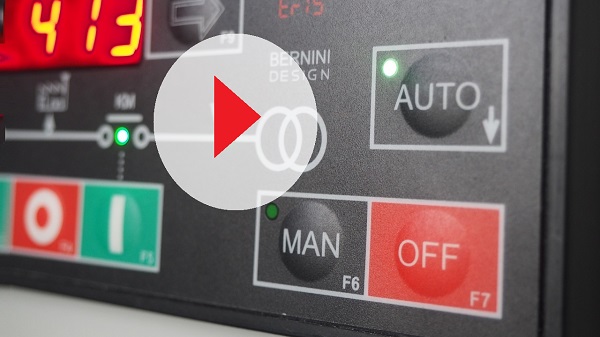
When a timer is running, the display indicates its status. Additional messages help you understand the various functions like Warm p, Cooling Down, Stop and many others. The OEM manual describes all details about them.
How to test the Auto Mains Failure?
The TEST mode is the best way to check the automatic functionality of the engine. It will not affect the transfer of the LOAD. You can optimise all parameters involved in the automatic mode, like the number of attempts, the starter timer, rest time, and stop time. The installation manual describes all the details about it.

The manual mode allows you the essential function required for testing the standby generator. All protections are active. As far as the contactors driving, you can not activate a contactor if the voltage and frequency are not within limits. If you have to carry out some special testing, you may temporarily disable the protections.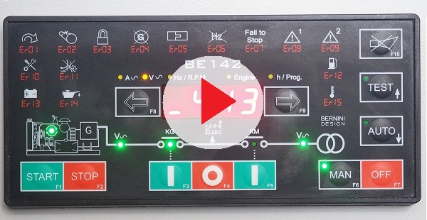
After finishing your testing, we recommend that you enable all protections before leaving the controller in automatic mode of operation. When a timer is running, the display indicates its status. Additional messages help you understand the various functions like Warm p, Cooling Down, Stop and many others. The OEM manual describes all details about them.
The Be142 AMF controller is user-friendly. Despite its complexity, with over 200 settings, it offers a smart and intuitive programming method. The video provides an example programming session.
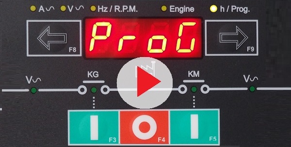 The Be142 AMF controller features the following group of adjustable parameters:
MAINS FAILURE AMD MONITORING PARAMETERS
GENERATOR CONTROL AND PROTECTION
ENGINE INTERFACE SETTINGS
INPUT-OUTPUTS PARAMETERS
SERVICE, RENTAL AND MAINTENANCE SETTINGS
MODBUS COMMUNICATION SETTINGS
REMOTE CONTROL SETTINGS
AMF Controller Wiring Diagram
The AMF panel fitted with a Be142 controller connects the LOAD to the generator via the KG. This is possible only when the MAINS is disconnected or, in other words, when the KM is open. The KM auxiliary contacts are closed when the KM is open. In this way, the AMF controller supplies the KG coil via a suitable pilot relay.
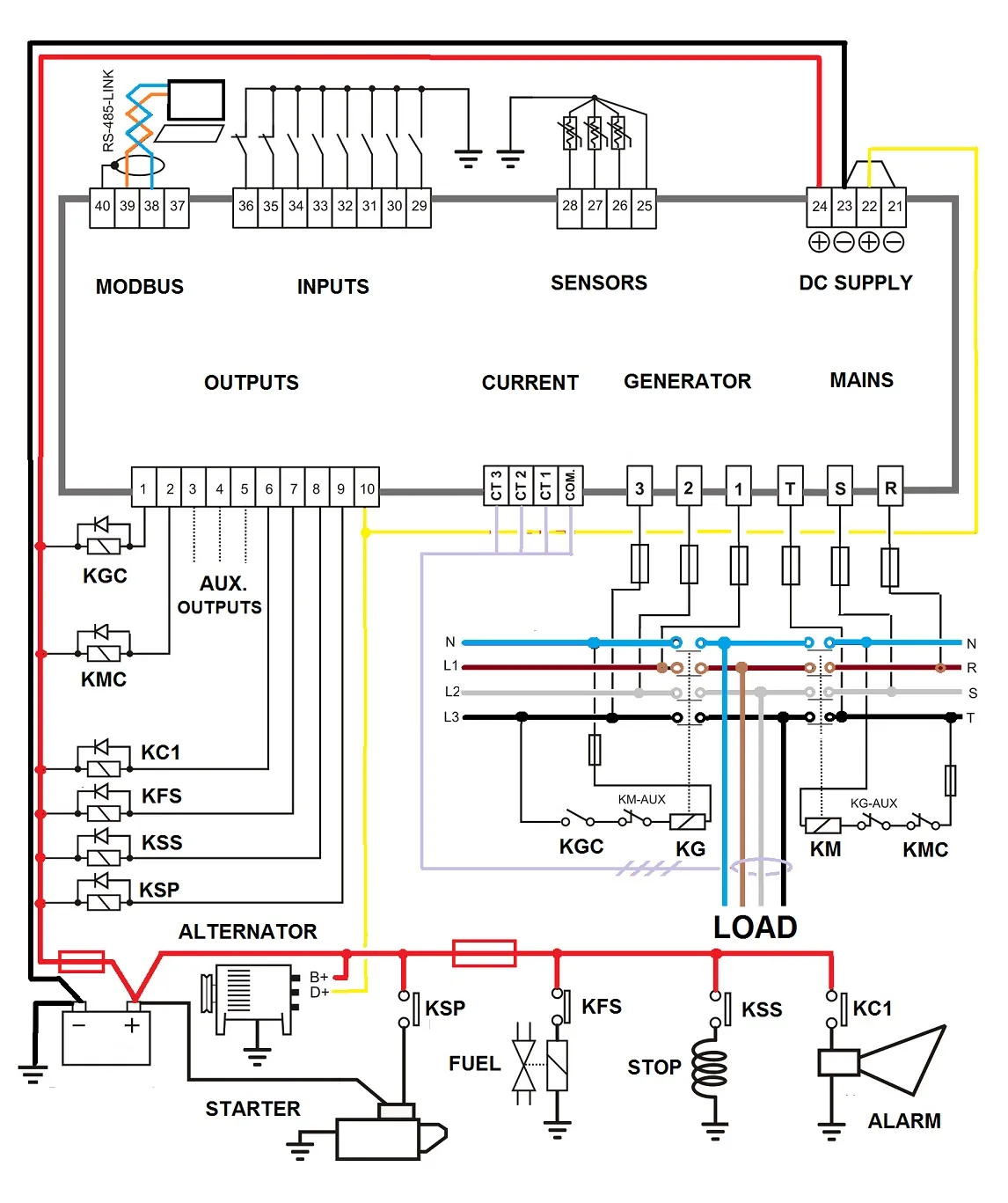
When switching the LOAD to the MAINS, the Be142 add a programmable DEAD-TIME. This will avoid sparks over voltages, and over currents when the LOAD is highly inductive. This is the case with big electric motors. Before energising a heavy LOAD, the Be142 AMF controller waits for the 'INTERLOCK-TIME'. This is set to 2 seconds by default. The inputs and outputs are fully configurable. We vividly recommend that you put flywell diodes on the output relays. Particular care is required when connecting the common ground of the sensors. Despite the Be142 having an internal ground sensing compensation, you will get the best result with good wiring.
MODBUS-RTU
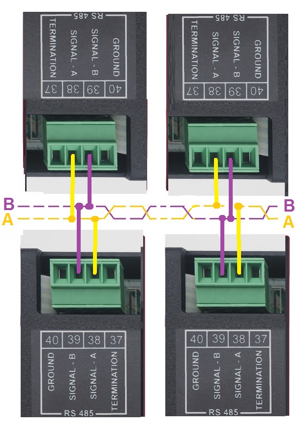
The BE142 AMF controller features an RS-485 serial interface capable of driving a 1000m twisted pair with 127 nodes. It completely supports the MODBUS-RTU protocol.
BE142 PROTOCOL & MODBUS REGISTERS
How does AMF controller offer accurate engine parameters readings
The secret lies in a deep understanding of the analogue sensor interface. The Be142 AMF controller features an analogue compensation guard wire. If you fail to connect this cable, the Be142 AMF controller triggers a warning alarm.
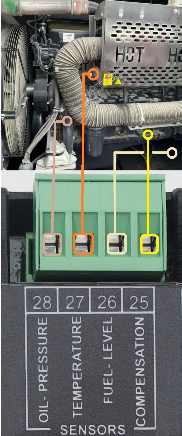
When dealing with a resistive sensor, you can not trust the battery minus supply wire. It carries different values of currents. In some cases, ageing increases the drop in voltage on the cable. In other words, only a few hundred millivolts can generate a 30% error in the temperature, oil or fuel level measurements. Bernini Design introduced the compensation concept many years ago. The sense wire senses the voltage drop on the supply wires and perfectly compensates for reading errors.
BE142 Remote Control Monitoring
Thanks to the RS-485 port, you can easily build a GSM-based AMF panel. You can monitor the vital parameters and, most importantly of all, you can remotely control your standby generator. In addition to GSM, you can directly connect the MODBUS to a PC-USB. You can run our free-of-charge software
VIA USB OR TCP-IP
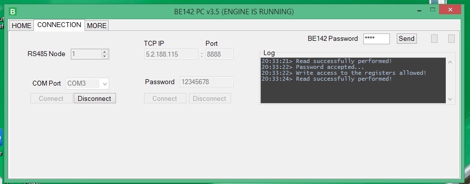
The software can be connected via a local COM PORT. In this case, you can use one of your USB ports. As an option, you can connect the software via TCP-IP. In this case, our software runs MODBUS over TCP-IP. You can use our TCP-IP server connected to your router.
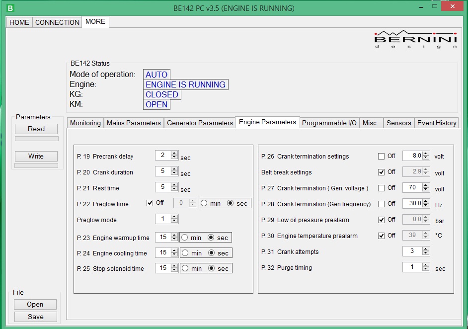
Our software allows the programming of the controller. There are pages dedicated to a specific range of parameters. In the following example, you can see the ENGINE parameters page.
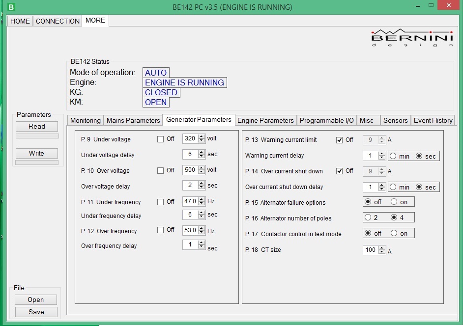
In this example, you see the GENERATOR parameter settings.
This is one of the landing pages that visualises the status of the standby generator.
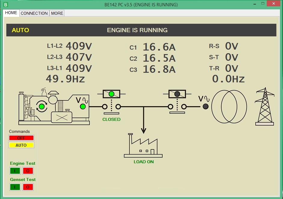
Supposing the standby generator is not in local MANUAL mode, you can control the generator directly from your computer. You can start the generator and transfer the load. In case of an alarm, the software opens the alarm page. You will analyse all details, and you can decide to restart the system or not. It depends on the importance of the alarm.
GSM Monitoring Solutions
You can install any kind of fuel level sensor. Despite the VDO-CONTINENTAL default setting, you can program your own 6-point response sense characteristic.
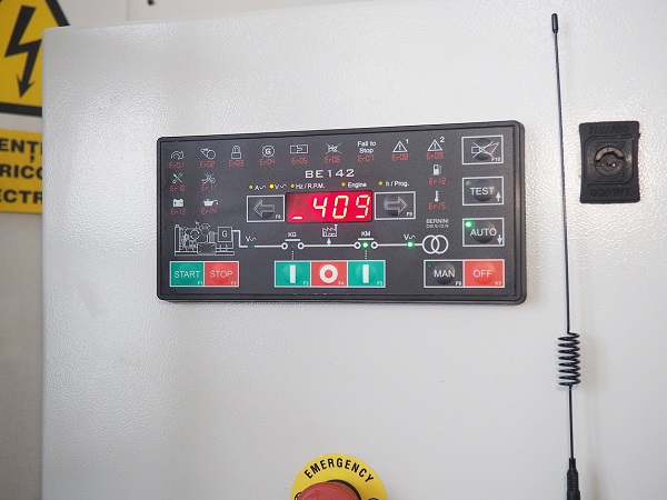
PREVENT FUEL THEFT ON YOUR GENERATOR
You will set the Low and high fuel level limits. The GSM system will send a notification about an unexpected fuel change when the engine is running or not.
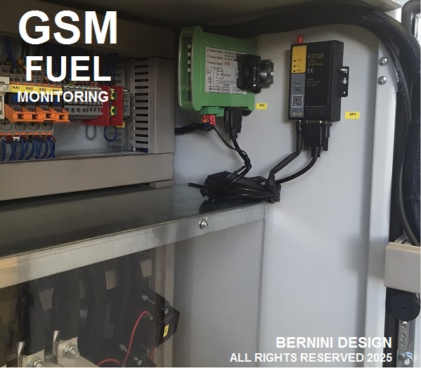
The Be148 SMS gateway is connected to the Be142 controller via RS-485. In other words, you can place the modem in a suitable and secure zone far from the controller. The Be142 embedded RS-485 can support a 1000m twisted pair cable.
THE ADD-ON GSM GATEWAY KIT
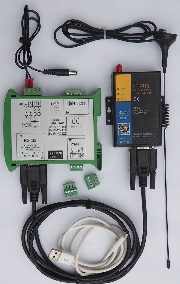
You can separately purchase the GSM KIT and add it to your AMF panel. Even though you can install the MODEM inside the panel, you may take care to position the antenna in a suitable position. With our SMS gateway, this is not an issue: you can install the MODEm itself up to 1000m away.
SMS SYNTAX
The GSM Gateway offers the following SMS commands:
STATUS It reads the status of the engine, mode of operation, status of the circuit breakers, and to read the power supply of the GSM GATEWAY module.
ALARM It requests information about active alarms. In case of no alarms, the GSM GATEWAY will return the message ‘NO ALARMS’.
GENV It sends a request to read voltages, currents and frequency of the Generator.
MAINS It sends a request to read voltages, currents and frequency of the Mains.
ENGINE It sends a request to read Battery Voltage, Speed, Oil Pressure, Fuel%,
Temperature (supposing Be142 configured for that), and h-meter.
CLEAR It clears a warning or it cancels a shutdown. Please note that in case of a
shutdown, the GSM GATEWAY will force the Be142 to enter the OFF mode of operation.
After that, you are required to take action. Otherwise, the controller will remain in OFF mode of operation.
OFF It commands the BE142 to enter the OFF mode of operation and eventually shuts down the engine. The command is ignored if the Be142 controller is in manual mode of operation.
AUTO It forces the Be142 to enter the AUTO mode of operation (only if it was in OFF mode). You cannot change a MODE of operation if the Be142 is locally in MANUAL mode. So, this command is totally ignored in the MANUAL mode of operation.
ENGINE TEST It makes the Be142 start the engine (only if Be142 is in AUTO mode of operation).
GENSET TEST It makes the Be142 start the engine and, when the electrical parameters are within the programmed settings, it will transfer the LOAD to the generator (allowed in AUTO mode of operation only)
STOP It stops the engine after an ENGINE TEST or GENSET TEST (only if Be142 is in AUTO mode of operation). This command is ignored if the engine is running for other reasons (for example, Mains Failure). In this case, to stop the engine, you have to use the command OFF. The Be142 will shut down the engine and will enter the OFF mode of operation. To restart, you are required to use the command ‘AUTO’.
Be142 controller application notes
AMF CONTROLLER CONTROLS TWO SEPARATE LOADS
Install the AMF controller to supply two separate loads from a single generator. The generator connects to the load affected by the power outage. This application is typical in private houses.
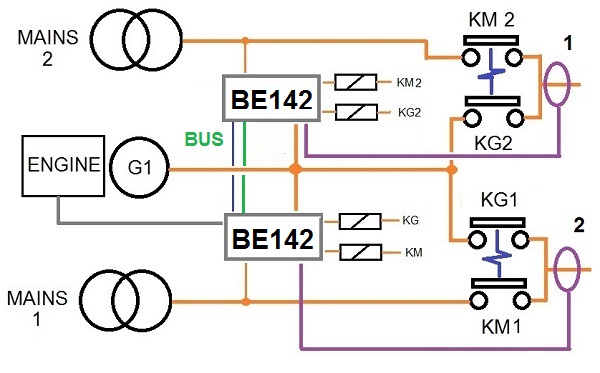
Two houses' power outages can be resolved by investing in a single generator. You must make two ATS panels of a suitable size. The two controllers communicate with each other with only a 2-wire hardware handshake.
ATS CONTROLLER IN A DUAL GENERATOR SYSTEM
The following wiring diagram presents the basic connections of a dual-generator AMF controller configuration. With Be142, you can connect two generators as an emergency standby to one single load. The BREAK-BEFORE-MAKE configuration is mandatory for the protection of the load. In case of a prolonged outage, you can set up ENGINE 1 as a master.
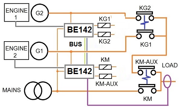
In case of starting failure, the second engine will start. The generator will supply the load. You are required to include the AMF controllers and transfer switches in the same cabinet. The two controllers communicate with each other with only a 2-wire hardware handshake.
UPGRADING THE BE42 CONTROLLER
When replacing a Be42 controller, you can install the Be142 because it features additional monitoring features.
The Be142 AMF CONTROLLER shares the same low-voltage I/O connection as the Be42 AMF CONTROLLER. The Be42 monitors three phases of MAINS but only two phases of the GENERATOR and one input for a current transformer. The Be142 is a fully three-phase AMF controller. The requirements from the connection point of view are shown in the picture.
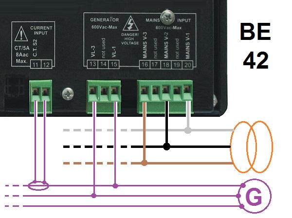
You must replace the old 5-pole MAINS connector with the new 3-pole connectors. After that, you must remove the old 3-pole connector for the generator and replace it with the new 3-pole. As you can see from the picture, Phase 3 of the GENERATOR remains unconnected.
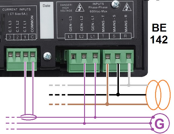
Finally, you are required to replace the code [0] with the code [1] in the parameter [P8]. The connections for CT2 and CT3 remain open. This will instruct the monitoring of a 3-phase system on the MAINS and only a 2-phase system on the GENERATOR. If the case, adjust the MAINS and GENERATOR parameters according to your application.
The Be142 auto mains failure inhibits the starter motor when the engine starts running. When the engine is not running, the voltage in terminal D+/WL of the charger alternator (input #22) is 0 V. As soon as the Be142 starts the engine, a voltage appears in the D+/WL terminal (0.8 to 2.5 V). When the engine starts running, the voltage of the D+/WL terminal increases by up to 3 V - 6 V. When the engine runs, the voltage reaches 14 V (28 V) needed to charge the battery. The safest point to disconnect the starter motor is between 6 V and 10 V. The default parameter of [P.26] is 8.0 V. This value is recommended for engines using 12 V batteries. For 24 V batteries, we recommend that you set the threshold to 16 V.
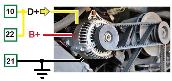
Make sure that the green ‘ENGINE RUNNING’ LED on the front panel is off during all of the starting attempts. The Charger Alternator voltage can be displayed in the 'Engine menu'. For Flywheel chargers, the reading is not accurate. The [P.26] setting, in this case, expresses only a proportional factor. The Be142 checks the GENERATOR voltage and frequency as well. Parameters [P.27] and [P.28] set the crank termination. These parameters do not affect the status of the green ‘ENGINE RUNNING’ LED.. Normally, using a diesel engine, we recommend enabling the BELT BREAK protection. This is accomplished by programming a voltage setting in the [P.26] sub-menu. To test the efficiency of this protection, disconnect terminal D+ from the charger alternator and connect it to ground. The BELT BREAK ALARM features a 15-second bypass timing.
Be142 AMF CONTROLLER SPECIFICATIONS
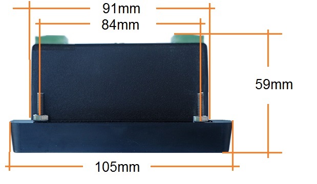
Overall Dimensions: 224mm X 105mm X 59mm
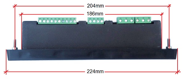
Panel Cut-out: 92mm X 187mm +/- 1mm
Fixing Hole Pattern: 204mm X 84mm
Operating temperature: -30 to +70 °C
Humidity range: 8% up to 90%
Simple Cut-out: the easiest solution
The simplest way to install the Be142 AMF controller is to make 2 standard holes for DIN96 square instruments. You will drill 4 holes for the M4 fixing screws. This will provide a vibration-proof long-term stability.
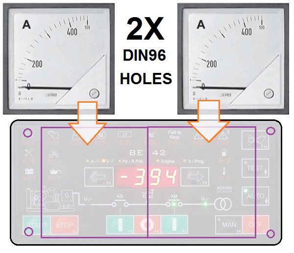
To get an IP62, you can seal the controller with non-acetic (neutral-base) silicon.
Display: 4 digits solid state
LED Indicators for all functions
12 Silver-Membrane-Type 100.000 actions life
Over 100 programmable adjustable settings
Connectors: removable terminal blocks as follows
I/O Connectors: removable terminal blocks 5.00 pitch 1x10-pole, 1x8-pole 1x4-pole
Supply Connector: removable terminal blocks 5.00 pitch 4-pole
CT Connector: removable terminal blocks 5.00 pitch 4-pole
Mains Vac Connector: removable terminal blocks 7.50 pitch 3-pole
Generator Vac Connector: removable terminal blocks 7.50 pitch 3-pole
Meets ECC 89/336, 89/392, 73/23, 93/68, IEC 68-2-6
DC Supply: 5.5/30Vdc, 50/100mA (max)
Supply spikes rating: 200V overvoltage (10/90 microsec)
OFF MODE standby current: 40mA
Protection: 200mA thermal electronic fuse
Operating Vac: up to 600Vac 3-PHASE
Electrical Measurements Precision: within 2%
Overvoltage Voltage: 2KVac
Static Outputs: NPN 200mA shoert-circuit-proof
Digital Inputs: 30V max (200V overvoltage 10/90 microsec)
CTs: up to 1000/5Aac
Bernini Design Srl
Industrial Area
46035 Ostiglia Italy
+39 335 70 77 148
bernini@bernini-design.com