
What is a Generator Monitoring System?
A generator monitoring system is the best solution when you need a full control of a power generator placed in a remote location. A remote location means that you do not have a visula of phisical conact with the generator: could be 100m of thousands kilomters. you will be aware of the status of the system in real time. You will get notified about the basic automation tasks and alarms. You can deeply browse all parameters, clear alarms or change the mode of operaionis. A generator remote monitring system is aprticularly mandatory in case of a standby generators, but also a simple stand alone generator: you can prevent a total battery failure.
Why use a generator monitoring system?
Generator remote monitoring enables proactive analysis of diesel sets to prevent emergency power failures before they happen. Bernini Design systems drastically reduce operating overhead and site-visit maintenance across industrial, telecom, and critical backup installations Targeted Dispatch: When an outage strikes, maintenance crews deploy knowing exact fault codes
and site conditions upfront—no blind diagnostic trips. Universal Scalability:From enterprise industrial plants to residential backup sets prone to silent cranking battery degradation, our rock-solid telemetry answers every operational "why."
How you can implement a generator monitoring system
There are two basic solution; a stand alone equipment that is a sort of a plug-and-play. In other words a system that is placed over an existing automation system. This is the best ans simpe way to gent information about your generator. The second and best solution is to install a controller with an embedded generaro monotoring system. In ths case you can totally take advantages of this tecnology; no rick of conflicts with other electronic equipemnt
How does a generator monitoring system actually work?
There are 3 basic solutions. TCP/ip, straigghr Modbus or GSM
While industry standardizers push fragile cloud dashboards and bloated mobile apps, Bernini Design builds deterministic, problem-proof telemetry: zero server downtime, zero subscription lock-in, and field-proven reliability over 25+ years (G2–G5 generations).GSM / SMS Text-Command TelemetryDirect cellular text-command architecture. No continuous data stream
required. for a complete diagnostic report straight to your phone. for instant state control. Works wherever cellular signal reaches. No app updates, no broker disconnects, no cyber-attack surface Remote monitoring via GSM, TCP/IP and Modbus are the recommended way to access a power generator from remote locations. The basic concept is to remotely transfer the control panel. In other words, you have a generator placed in Argentina, but from your office in Australia, you will act as if you were in front of the generator. Bernini Design provides a generator remote monitoring equipment, hardware, and software to manage a Diesel Generator placed in a Base Transceiver Station (BTS).
It is about a shelter or a building that includes fundamental equipment that allows wireless communication between the user equipment and a network. The user equipment may include mobile phones, tablets, radio equipment, and computers. This includes wireless Internet connectivity. The purpose of a diesel generator monitoring system is to reduce the operating costs for maintenance. When an outage does occur, service personnel can be dispatched with valuable information regarding what problems they may encounter on-site. A diesel generator monitoring system plays an important role in preventing and reducing network outages caused by generator troubles. You can set pre-alarms, and you can modify the settings of the engine or generator. This will avoid severe damage to the system. The DIESEL GENERATOR MONITORING SYSTEM can monitor the parameters of the utility power to the site, rectifiers & batteries, air conditioner, and other hybrid power types of energy sources.
TCP/IP GENERATOR REMOTE MONITORING
TCP/IP Direct-Socket Server Architecture Bernini’s TCP-IP server delivers a state-of-the-art, deterministic internet-based connection built with hardware-level security against intrusion and automated flood/loop attacks. Ethernet cable from TCP-IP server to router; twisted-pair RS-485 up to **1000m** distance from generator controller to TCP/SERVER.
<Power & Environment:Engine battery or isolated power supply up to **30V**;
ultra-low consumption of **100mA** at full speed; operating range **-25°C to 70°C**.
Commissioning: Direct setup per user manual—no cloud middleware or mystery tunneling.Need fancy color touchscreens and cloud dashboards? Look at Deep Sea or ComAp. By using our TCP-IP server, you built a state-of-the-art real-time internet-based monitoring system. Our TCP-SERVER features all hardware security components to prevent
TCP-IP SERVER
329€
FREE SHIPPING
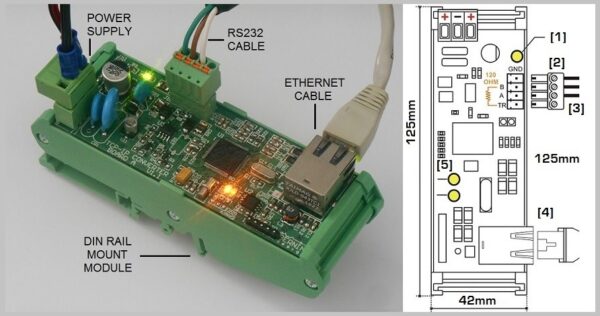
You are required to connect the TCP IP server to the router by using an Ethernet cable. You must connect the RS-485 cable of the generator controller, to the TCP IP server. The RS-485 connection allows up to 1000m distance between the generator controller and the TCP/SERVER. Both types of equipment can be connected to the engine battery. The power consumption of the TCP IP server is only 100mA when operating at full speed. The module can operate in a wide temperature range of -25 to 70 degrees Celsius. Follow the steps in the user manual to configure the TCP IP server.
INDUSTRIAL GENERATORS GSM MONITORING
The top results of a good GSM monitoring system are obtained when there are no compromises on the quality and performance of the generator controller. The Be124 GSM system is the best example.

The diesel generator remote monitoring via SMS is the simplest, user-friendly monitoring solution. Firstly, it is particularly used when Fuel Level monitoring is an important issue. This is the case for mobile operators in areas subjected to prolonged power outages. The generators are always located in remote places. Secondly, fast-responding remote equipment together with good diesel fuel sensing devices can prevent theft and will allow you a better scheduler of refuel visits. This will prevent the shutdown of a remote site due to running out of fuel. The Bernini Design generator controllers feature a programmable automatic 'FUEL CHANGE' notification.
BE124 SMS MONITORING USER MANUAL
The kit consists of the following parts:
1) The F1403 industrial modem
2) GSM antenna
3) Be148 gateway module
4) Set of cables, accessories and user manual
PURCHASE THE GSM GATEWAY KIT FOR YOUR APPLICATION
When you make an order, specify the controller you are willing to connect: Be124, BeK3 or Be142. Each controller features a different set of MODBUS registers and a suitabe set of SMS commands.
BE148 GSM GATEWAY
349€
FREE-SHIPPING WORLD-WIDE
You can pay online or ask for a pro forma invoice and pay via bank transfer
SUPPORT
+39 335 70 77 148
bernini@bernini-design.com
DIESEL GENERATOR GSM REMOTE CONTROL KIT
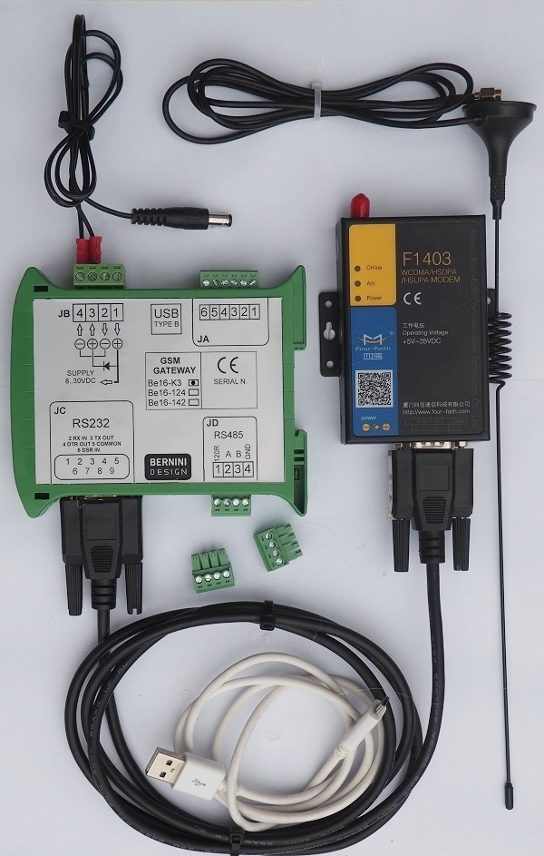
The kit feautures a GSM antenna, an RS232 communication cable, an RS485 cable, a modem power supply cable, and a kit set of a removable connectors. By folllowing the instruction manual you can set up the system in a few minutes. If the place in wich the generator is installed is not very well covered by the GSM network, you can install the gateway as fr as 1000 meters from the controller. In this way you can provide optimal signal to the modem antenna.
15KVA AMF PANEL STUDY CASE
When it comes to Automatic Mains Failure panels, we recommend the BeK3 GSM kit. After installing the system, you can get full control of the AMF PANEL using SMS commands. In this example, a 15kVA AMF panel.
CLICK ON THE IMAGE TO ACCESS MORE DETAILS
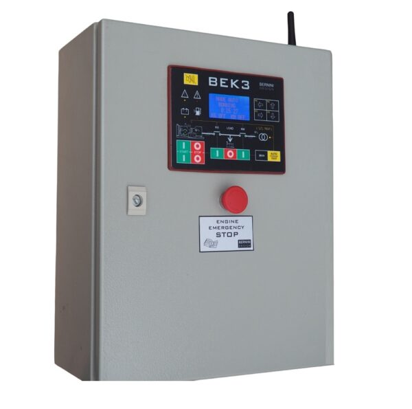 In the above example, the GSM kit is embedded in the panel. The antenna is placed on the top of the panel. By using the Be16-K3 gateway, you are able to fully control the panel functionality. You can start the generator via an SMS command.
15KVA AMF PANEL WITH GSM MONITORING OPTION
1190€
FREE SHIPPING TO EU
DELIVERY TIME 30 DAYS
Using your mobile, you can transfer the LOAD from the MAINS and the GENERATOR. Not mentioning that you will receive detailed notifications about all events. Check the user manual for all available SMS commands.
BEK3 AMF PANEL GSM MONITORING USER MANUAL
MODBUS MONITORING
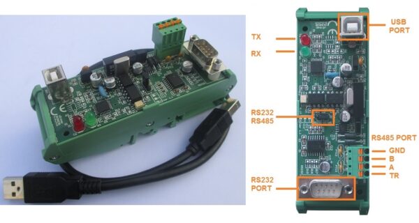
Direct MODBUS communication is the easiest way to control and monitor a diesel generator. Connect the MOD-BUS to the USB converter to a Bernini Design generator controller. Use a twisted pair cable. The <be124 generator controller, for example, can drive a cable as long as 1000 meters. Connect a computer with a USB interface. Run the Bernini Design application software to connect the computer to the generator.
RS485-USB
149€
FREE SHIPPING
Wireless Generator Monitoring System
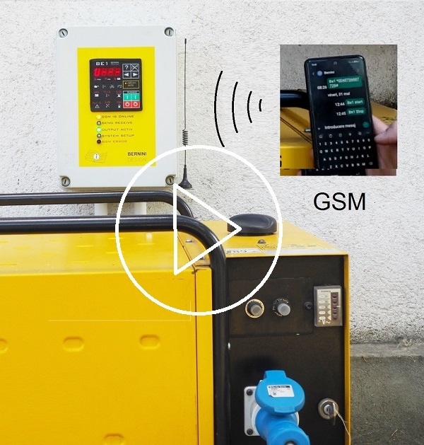
You can purchase a "ready-for-use" generator GSM-BASED start-stop panel. This is suitable when you need a trustworthy GSM monitoring system. Follow the link on the video description. You can purchase this product online.
Generator Auto Start Stop GSM Kit
MAKE YOUR OWN COST-EFFECTIVE GENERATOR START-STOP REMOTE CONTROL. USE SIMPLE SMS TO START AND STOP WITH FULL FEEDBACK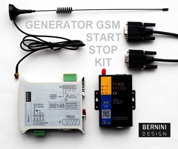
You can easily start and stop your generator by sending an SMS.
The Be148 can interface with the most common auto-start module on the market, but you can add a pilot relay and make a smart Auto Start Module.
BE148 GSM RELAY
199€
FREE-SHIPPING WORLD-WIDE
You can pay online or ask for a Proforma Invoice and pay via bank transfer
SUPPORT
+39 335 70 77 148
bernini@bernini-design.com
HOW IT WORKS
The Be148 features an analogue input to detect if the engine is running. You will get feedback notifications for all available SMS commands. The Be148 has a built-in watchdog that keeps the GSM link healthy. The watchdog immediately reset and re-configure the modem in case of failure. The Be148 is suitable for starting any diesel generator fitted with its automatic start module. Usually, the supply for the Be148 is the same of the automatic start module: the engine's battery. This could be 12V or 24V.
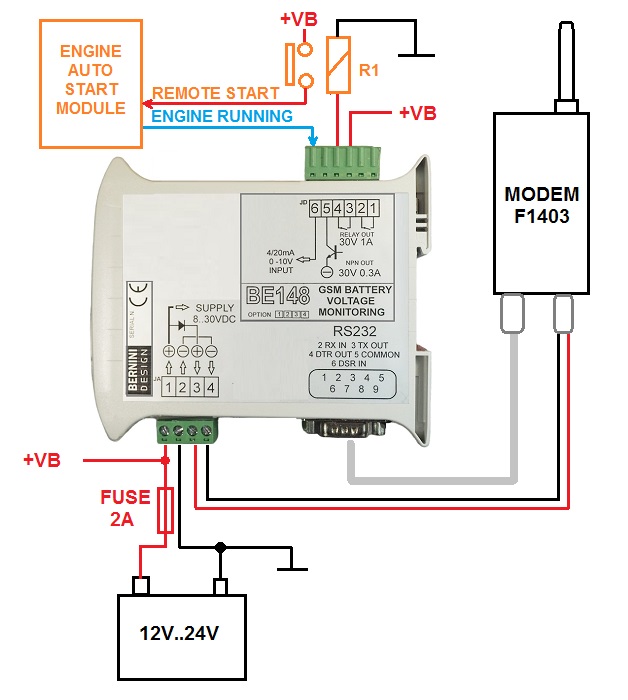
RECOMMENDED GENERATOR REMOTE GSM DIAGRAM
In this example, the JD3-4 output drives the relay R1. The R1 relay will instruct the AUTOSTART MODULE to start the engine. A positive voltage, over 8Vdc, is required to trigger the ‘ENGINE RUNNING’ input. After receiving the STOP SMS, the relay R1 de-energizes. The engine will stop according to the AUTOSTART MODULE settings. Terminals #1, #2 and #5 are used for special applications (contact us).
Zona Industriale
46035 Ostiglia Italy
bernini@bernini-design.com
0039 335 70 77 148
Zona Industriale
46035 Ostiglia Italy
bernini@bernini-design.com
0039 335 70 77 148
Zona Industriale
46035 Ostiglia Italy
bernini@bernini-design.com
+39 335 70 77148