BE142 AMF CONTROLLER
The Be142 is a 3-phase AMF controller. It upgrades the most popular Be21 and Be42 controllers.
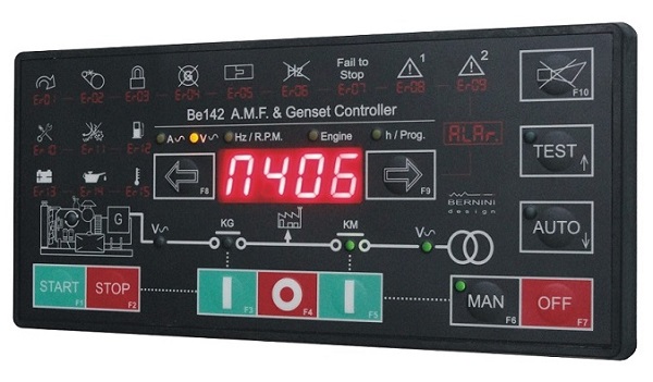
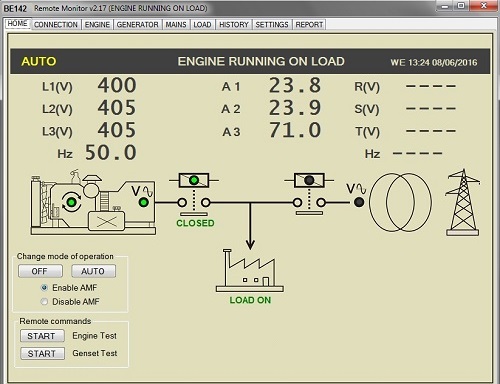
A high-luminosity display shows parameters, alarms, and operating functions. The AMF controller Be142 interfaces with resistive or digital sensors. It measures Vac, Aac, Vdc, Hz, hour count, R.p.m., Oil Pressure, Engine Temperature, Battery Vdc and Fuel Level. Software for remote monitoring is also provided free of charge.
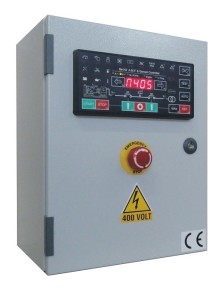
A COST EFFECTIVE PANEL EXAMPLE USING THE BE142
The Be142 provides MODBUS via RS485. The AMF controller Be142 complies with NFPA-110 / NFPA-99. Install our TCP-IP server to monitor and control the Be142 via the INTERNET. An option for remote control by GSM is also provided. We provide support for making your own AMF Control Panels. The Be142 AMF controller is the best choice when you are required to manufacture professional & general purposes AMF panels.
PURCHASE ONE PIECE
329€
FREE-SHIPPING
PURCHASE 2 PIECES
229€/each
FREE-SHIPPING
THE BE142 AMF CONTROLLER WIRING DIAGRAM
This is the typical BE142 control panel circuit diagram. You can observe the connections of the current transformers wired on the load side. This allows the Be142 to display the generator current when a circuit breaker is closed. So, you can read the current into the load even when connected to the power utility.
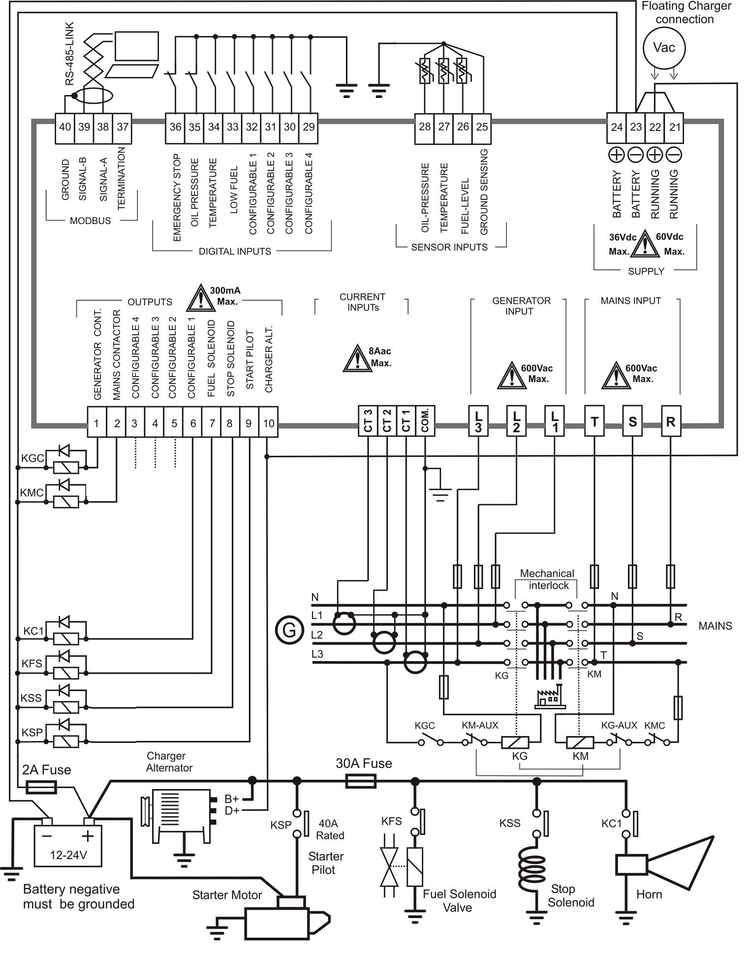
You can set up alarms (warning or shutdown) in case of an over-current. The Be142 will trigger the alarm only when connected to the generator. You can set up important protections for Over/Under frequency, voltage, and many others. Add only a few relays to interface with all kinds of engines: gas-gasoline-diesel. You can observe the RS485 connection as well. This will expand the monitoring options via GSM and TCP/IP.
The Be142 is designed to drive two contactors. A good practice practice, in addition to the electrical interlock, is to use a suitable mechanical interlock. This will avoid back-feeding in case of damage to the Be142 controller. You can connect analogue or digital sensors directly to the Be142 inputs. The output of the Be142 is suitable for automotive relays 12V or 24V (according to the engine's battery). The Be142 outputs are short-circuited proof, but we recommend that you connect all the time with flywheel relays.
THE Be142 CONTROLLER REAR VIEW
All connections are made via removable female connectors.
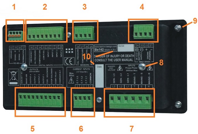
1) RS485 4-POLES PLUG 2) DIGITAL INPUTS 3) ENGINE INSTRUMENTS INPUTS 4) POWER SUPPLY AND ENGINE RUNNING CONNECTIONS 5) GENERAL PURPOSE OUTPUTS 6) CURRENT TRANSFORMERS CONNECTIONS 7) MAINS AND GENERATOR VOLTAGE CONNECTIONS 8) REAR COVER SCREWS 9) 4 X M4 FIXING NUTS
BE142 MODBUS REMOTE MONITORING
Thanks to the built-in RS485 serial interface, you can easily communicate with the controller by using the standard MODBUS protocol. On the hardware layer, you may need a twisted pair cable able to carry a 19600 baud rate. We can supply an industrial-grade MODBUS-USB converter capable of extending the connection up to 1000 meters.
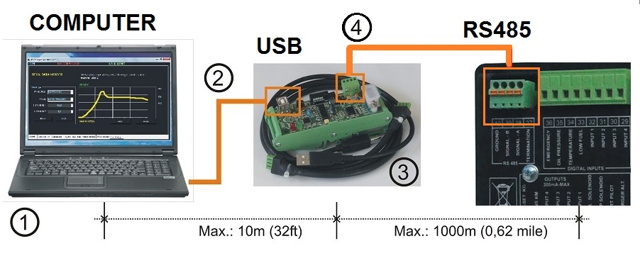
PURCHASE THE USB CONVERTER
129€
FREE-SHIPPING
Software for remote monitoring is offered free of charge. It runs on all Windows-based systems.
UPGRADING A BE42 CONTROLLER WITH BE142
The Be142 shares the same low-voltage connection as the Be42 controller. The Be42 monitors 3-phase of MAINS but only two phases of the GENERATOR. The Be42 features only one input for a current transformer. The Be142 is a fully 3-phase AMF controller. When you are going to replace an old Be42, we recommend that you install the Be142. It is not only 3-phase, but it has additional features about MAINS and GENERATOR monitoring. You can see in the picture the requirement from the connection point of view.
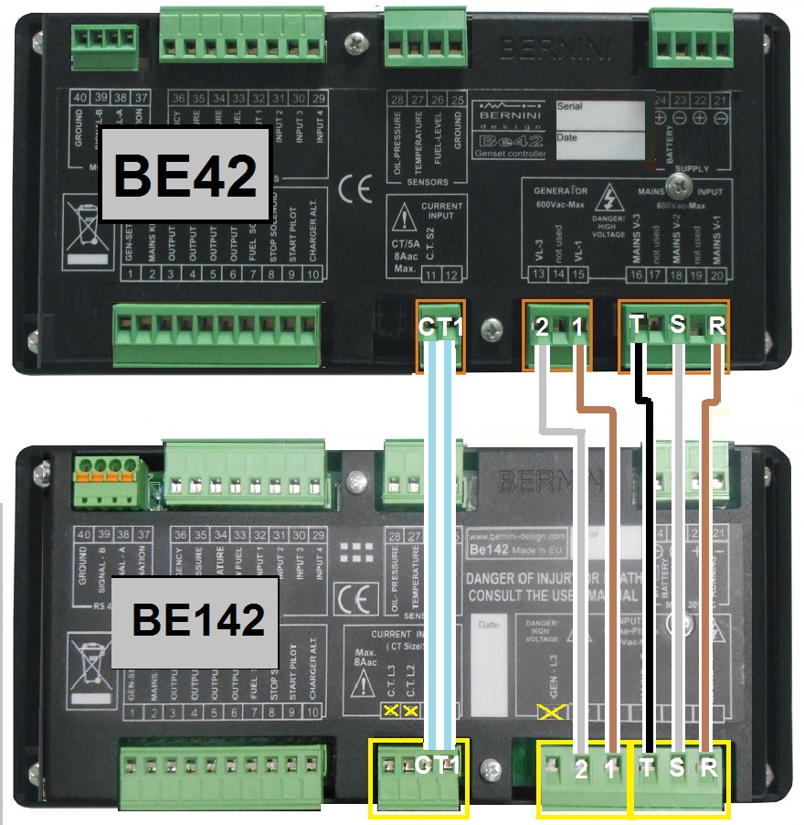
You are required to remove the 3 wires of the MAINS connection. You must replace the old connector with a 5-pole with the new one with 3 poles only. After that, you remove the old 3-pole connector for the generator and replace it with the new one. As you can see from the picture, Phase 3 of the GENERATOR remains unconnected. Finally, you are required to replace the code [0] with the code [1] into parameter P(. This will instruct to monitor a 3-phase system on the MAINS and only 2-phase on the GENERATOR. You will benefit of a new updated software running on your standby system.
BERNINI DESIGN SRL
Zona Industriale
46035 Ostiglia Italy
0039 335 70 77 148

