LOW BATTERY GENERATOR AUTO START MODULE

The Be1 is an Universal Generator Controller with embedded Low Battery Generator Auto Start software. 

refurbish your generator today

You can set up low battery voltage start and high battery voltage stop settings. No more headaches, no more fears of failing to start attempts.

VIDEO TUTORIAL ABOUT LOW BATTERY START


KEEP IT SIMPLE!

Using the Be1 controller you can set a LOW BATTERY VOLTAGE threshold (1). The engine will start after a programmable delay (3).

setting up a low battery auto start module

When the battery rises above the HIGH BATTERY VOLTAGE threshold (2), the delay timer (4) will start to count. When the timer (4) will expire, the engine will automatically stop.


LOW BATTERY START MODULE RECOMMENDED CONNECTION 

GROUNDED IN THE CORE OF ELECTRICAL RULES

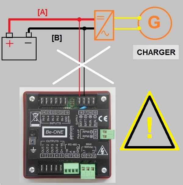
Do not connect the device as indicated in the following picture. When the charger delivers current, the drop of voltage on wires [A] and [B] generate high errors, as much as 1V, in the reading. Connecting to the correct point of the measurement cable is vital for a LOW BATTERY AUTO START module.

Wrong Low Battery Auto Start Circuit Connection 600px.jpgThis is the correct way to connect the Be1 Low Battery Auto Start Module. The measurement cables are directly connected to the battery. This connection will allow precise battery voltage measurements.
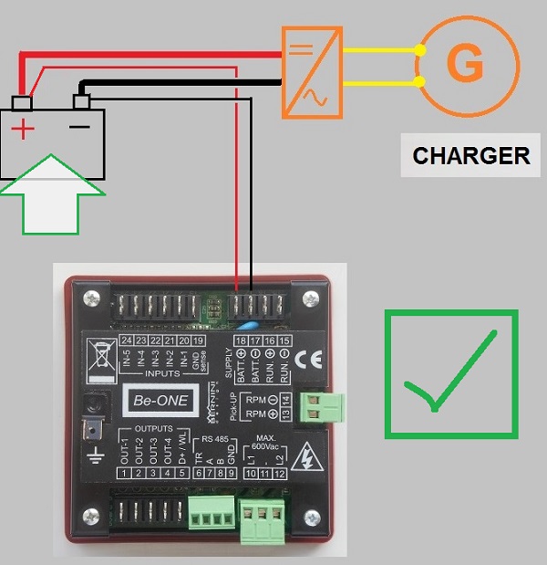
CORRECY WAY TO CONNECT THE LOW BATTERY START MODULE


USER-FRIENDLY SETUP INSTRUCTIONS

1 Remove the DC supply. Push and hold the button [0], turn the supply on and hold the button [0] until the message [Lobt] is displayed.

2 Simultaneously push [?] and [Auto] to increase the low battery threshold. simultaneously push [?] and [ I ] to decrease the low battery threshold.

3 Push the button  [→] to select the [Hibt] threshold. Simultaneously push [?] and [Auto] to increase the high battery threshold. simultaneosly push [ ? ] and [ I ] to decrease the high battery threshold.

4 Simultaneously push [ACK] and  [→] for about 5 seconds.

5 Enter the programming mode and program an output (example output 4) with the option [15]. You may add a delay before starting and stopping by adjusting the parameters [P0] and [P1] (see Table 7.00). Save your settings by simultaneously pushing the  [ACK] and [→] pushbuttons

6 Connect output 4 to the remote input (example input 4).


WHAT ABOUT BATTERY MONITORING FROM A REMOTE LOCATION?

This is no longer an issue. We can improve the performance of the Be1 by adding a GSM gateway and multiband  GSM modem. If not enough, you can benefit from the RS485 serial interface supporting the MODBUS-RTU protocol. You can connect a controller as far as 100m. You can connect TCP-IP routers and servers. The applications will be limitless.

DEMO VIDEO GSM REMOTE START
Low battery auto start module features remote monitoring
In the above video, you can see how the Be1 GSM-based panel works. You can purchase the panel ready for use. The panels include all relays capable of directly interfacing with your engine. We can offer the Be1 GSM kit. It consists of the basic parts: the Be1 controller, the SMS gateway, and the GSM modem with antenna and cables. Visit the page

GSM  GENERATOR CONTROL PANEL


WHAT ABOUT THE CONNECTION TO ENGINE AND GENERATOR?

The LOW BATTERY START feature is one of the adjustable control functions of the Be1 Generator Controller. You can find all adjustable settings in the INSTALLATION MANUAL.

BE1 LOW BATTERY AUTO START INSTALLATION MANUAL

To interface with the engine you must add a suitable pilot relay. The start circuit may require as much as 30 amps. The Be1 directly interfaces with all kinds of digital or analogue sensors. In addition to Voltage and frequency monitoring, you may use a pickup to detect the engine's rotational speed.


THE BE1 VIDEO TUTORIALPURCHASE THE BE1 GENERATOR CONTROLLERBE1 GENERATOR REMOTE START INSTALLATION MANUAL


ONLINE PURCHASE

BE1 BEST OFFER 99 USD

THIS WEEK

17-23 JUNE

PURCHASE NOW

$99

(91€)


[email protected]

WhatsApp +40721241361

Gsm +39 335 70 77 148

SALE TERMS

30-Day Money Back Guarantee And Cancellations

MAKE YOUR OWN GENERATOR START STOP PANEL TODAY

Make your own generator control panel today

GENERATOR AUTOMATIC START-STOP CONNECTIONS TUTORIAL

The Be1 is the perfect choice for a gasoline generator. It interfaces with the Flywheel generator to trigger a crank termination. The Be1 offers two options to stop the gasoline engine: STOP SOLENOID or FUEL SOLENOID.

GASOLINE PORTABLE GENERATOR REMOTE START KIT

This output energizes when you want to stop the engine. The contact of the relay will close to ground the ignition terminal on the spark generator remote start. You can easily find this terminal because it is normally connected to the STOP switch on the body of the gasoline generator.  The engine stops when the spark plug is off. You can adjust the time for STOP SOLENOID.  You can also use the FUEL SOLENOID by connecting a relay to the output [1]. The engine runs only when the FUEL SOLENOID output is active. This is an 'ENERGIZED TO RUN' output. The best solution is to use both: STOP SOLENOID & FUEL SOLENOID. The start circuit is quite similar to a diesel engine. Finally, connect the starter pilot relay to the output [2].


INPUT CONNECTIONS and POWER SUPPLY

Even though all inputs are freely programmable in digital or analogue mode, the Be1 is supplied with factory defaults. The input [4] is set for remote start input in normally closed mode. Connect all switches committed to starting the engine in a logical OR. When at least one input is connected to the ground, the Be1 will instruct the engine to start. When all input switches are open,t the Be1 will instruct the engine to stop.

connecting the remote start input

The input [5] is set as normally closed contact. It will trigger the emergency alarm. This input is reserved for the emergency button. All inputs when set in digital mode, only accept dry contacts. It must be isolated from an external source of voltage.

Be1 SENSORS and Battery connections

The default programming for INPUT [1] is OIL PRESSURE SWITCH, for INPUT [2] is FUEL LEVEL SWITCH, and for INPUT [3] is ENGINE TEMERATURE SWITCH. Connect dry contact only. Configure the inputs into analogue mode if the engine features analogue sensors. For each input, you can program a 5-point response curve.  The power supply must be connected to terminals [17] and [18]. We recommend that you protect the wires with 4 Amps FUSE. The Be1 controller has its own electronic fuse of about 500mA. The Be1 accept 12V or 24V batteries.


OUTPUT CONNECTIONS

The Be1 offers four programmable outputs. Each output can be associated with one of the 31 available options. Default programming sets the output for the most common applications, such as fuel solenoid, start, and pre-glow. The outputs are short circuit proof, the logic is negative. The output is designed to drive automotive relays. In other words, you must connect the other side of the relay coil to the battery plus. To avoid electrical noise we always recommend that you use the flywheel diodes.

the Be1 controller output connections


CHARGING ALTERNATOR CONNECTIONS

If you can not connect the flywheel generator, the Be1 features adjustable settings to terminate the crank from the Voltage and frequency of the GENERATOR. You can also connect a pickup to get an accurate reading of the rotational speed. Also in this case do not worry about it. The Be1 can calculate the RPM from the alternator frequency.  You only have to set up the number of poles of the alternator. The connection for sensors, analogue or digital, is indicated in the wiring diagram.

BELT ALTERNATOR

The terminal [5] supplies excitement current to the alternator. Terminal [15] must be connected to battery minus.

BELT ALTERNATOR CONNECTION

BELT  ALTERNATOR MONITORING

The auto-start generator module automatically terminates the crank when the engine starts running. The Be1 provides an exciting current for the charger alternator.  When the engine is not running, the voltage of the terminal D+/WL is 0V (in your car, before starting the engine, the red 'DYNAMO LAMP' turns on).

Generator remote start Kit Belt Driven Alternator Monitoring

As soon as the Be1 controller starts the engine, a voltage appears in the D+/WL terminal and when the engine runs normally, the voltage of the D+/WL terminal increases by up to 13-14 V (in your car, having one side of the lamp connected to the battery plus, the red 'DYNAMO LAMP' in the dashboard turns off ). The safest point to terminate the crank is between 6V and 10V.

FLOATING ALTERNATOR

This is the typical connection for a gasoline engine or a 3000RPM small diesel generator.  The wires are floating. For this reason, you must not connect the terminal [5]. The principle of detecting an engine's running status is similar to a belt alternator.

FLYWHEEL ALTERNATOR

The display indicates the average voltage supplied by the flywheel alternator when the engine runs at a nominal rotational speed.

BE1 GENERATOR REMOTE START INSTALLATION MANUAL

ARE THERE OTHER OPTIONS TO MAKE AN AUTOMATIC LOW-BATTERY START?

DEFINITELY YES!

Add a simple low-battery voltage monitoring relay if your generator already features an automatic start module. It is about a box that activates a relay when the battery is low. It deactivates the relay when the battery is fully charged.

cost-effective low battery voltage monitoring relay

It would help if you connected the relay output to the remote start input of your AUTO START module. You can read more and purchase the

BE48 BATTERY MONITORING RELAY


THE LOW BATTERY AUTO START GSM KIT

If you are a master id D:I:Y you can purchase the GSM kit. It consists of Be1 generator controller, SMS gateway, multi-band GSM modem, antenna, and complete set of cables.

Generator Auto Start GSM kit

PURCHASE THE GSM AUTO START KIT


LOOKING FOR SUPERIOR PERFORMANCES?

THE BE124 CENTURION GENERATOR CONTROLLER

THE BE124 CENTURION GENERATOR CONTROLLER


BERNINI DESIGN SRL

Zona Industriale

46035

Ostiglia Italy

[email protected]

+393357077148