NFPA20 Fire Pump Controller
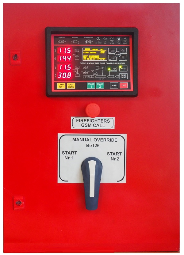
Bernini Design is specialized in manufacturing NFPA 20-compliant controllers. The BE126 is a combined NFPA 20 fire pump controller and automatic and manual diesel engine fire fighting system controller.
EXTENDED TEMPERATURE RANGE -30°C/+70°C
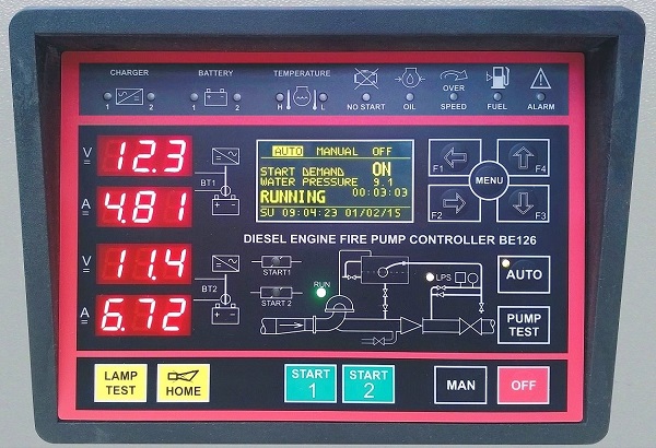 The BE126 is a multiprocessor automatic and manual diesel engine fire-fighting system controller. It meets or exceeds NFPA 20 standard requirements. Secondly, it includes fire pump alarms and signalling means, which ensures maximum control panel performance. In conclusion, the Be126 fire-fighting system controller is suitable for use in locations subject to high moisture, such as a damp basement or others. The Be126 offers two displays completely independent of each other.
Are you looking for an Original Replacement for a Be26 diesel fire pump controller?
This controller was introduced in 1990 as the first processor-based NFPA20-compliant firefighting controller. It is no longer manufactured, but we can manufacture a replacement upon request. Visit the following page.
THE BE26 DIESEL FIRE-FIGHTING PUMP CONTROLLER
Be126 versus Be26
The key switch is no longer mandatory according to the latest NFPA20 regulation. The Be126 features a mode of operation selection via push buttons and static outputs instead of relay outputs. Inputs for analogue measurements have been added together with the engine battery's direct monitoring via MODBUS, Finally, many features like CANBUS and DATA LOGGER have been introduced.
BE126 FIRE PUMP CONTROLLER KEY FEATURES
BE126 NFPA20 INSTALLATION MANUAL
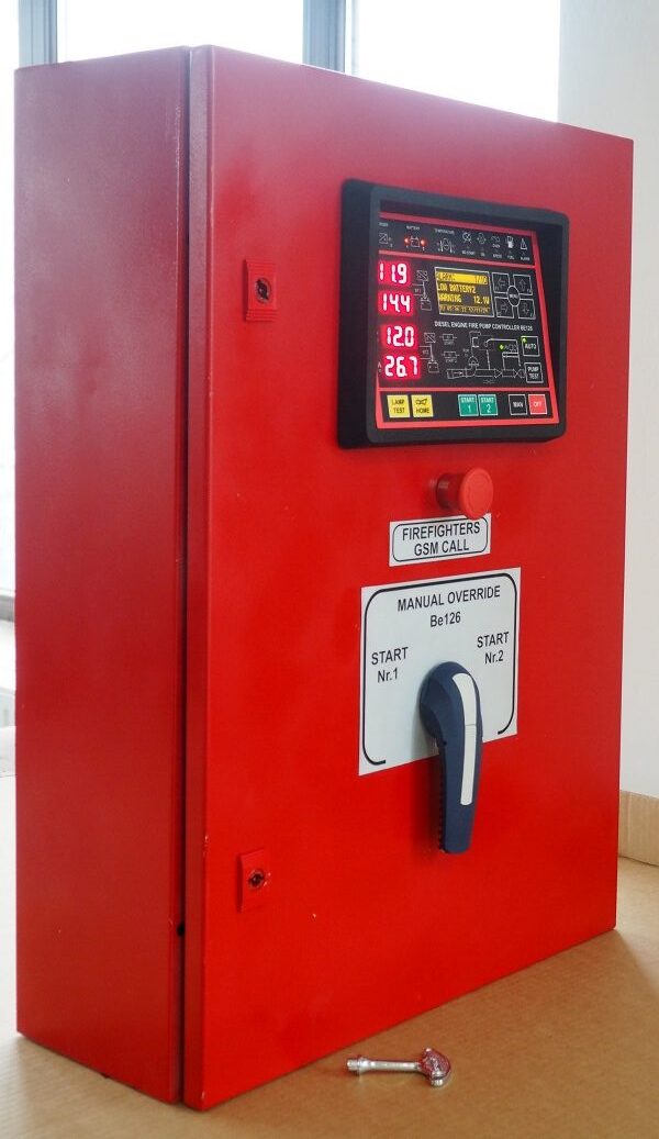
The design of NFPA20-compliant diesel engine fire-fighting controllers is a speciality of Bernni Design company. We offer the following extraordinary features.
DISPLAYS VOLTAGE & CURRENT OF THE TWO BATTERIES
FOUR 3-DIGIT LED DISPLAY AND OLED GRAPHIC DISPLAY
ORGANIC GRAPHIC DISPLAY WORKING -30°C UP TO +70°C
MONITORS UTILITY POWER V-HZ-SEQUENCE & OTHERS
BATTERY, PUMP, MAINS & ENGINE INSTRUMENTS
GSM ALARM ALERTS WITH TIME STAMP
REDUNDANT MEMORY SYSTEM WITH 200 LOG EVENTS
EMBEDDED WATER PRESSURE, 30-DAY DATA LOGGER
ACCEPTS DIGITAL AND ANALOG PRESSURE TRANSMITTER
FEATURES RS485, RS232, CANbus (SAE J1939 COMPATIBLE)
THE IMPRESSIVE SET OF ADJUSTABLE PARAMETERS
WE LOVE THE MOTTO "KEEP IT SIMPLE". BUT, FOR THE LOVERS OF COMPLEXITY, THE B126 FEATURES AN INCREDIBLE SET OF ADJUSTABLE PARAMETERS. HERE YOU SEE SOME EXAMPLES.
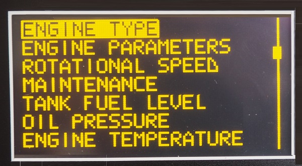
Open the ENGINE TYPE menu. A sub-menu lists all kinds of engines: conventional or with ECU. In this example a choice for VOLVO EDC3 engine.
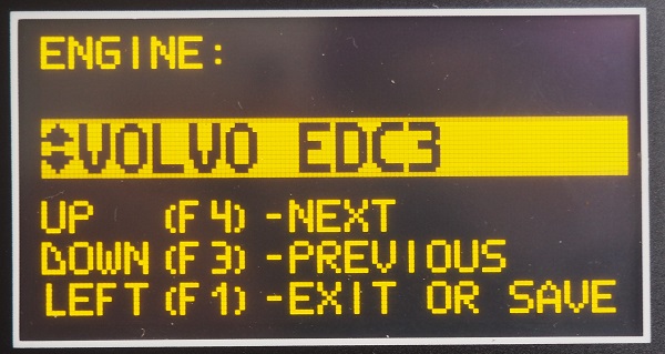
By opening other menus, you can set up all kinds of allowed shutdowns and warnings about fuel, temperature, oil pressure and maintenance schedule.
IN-FIELD TROUBLESHOOTING FEATURES
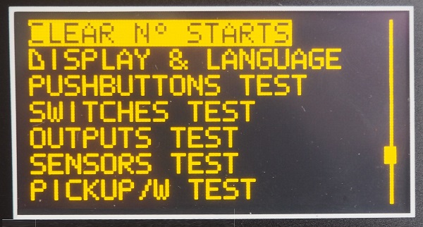
The Be126 can assist you in troubleshooting all kinds of failures. You can test each input, analogue and digital, all outputs and the pushbuttons on the front panel.
THE BE126 FRONT FASCIA
[1] ALARMS PANEL [2] GRAPHIC DISPLAY [3] NAVIGATION PUSH BUTTONS [4] MENU PUSH BUTTON [5] AUTO PUSH BUTTON [6] TEST THE PUSH BUTTON
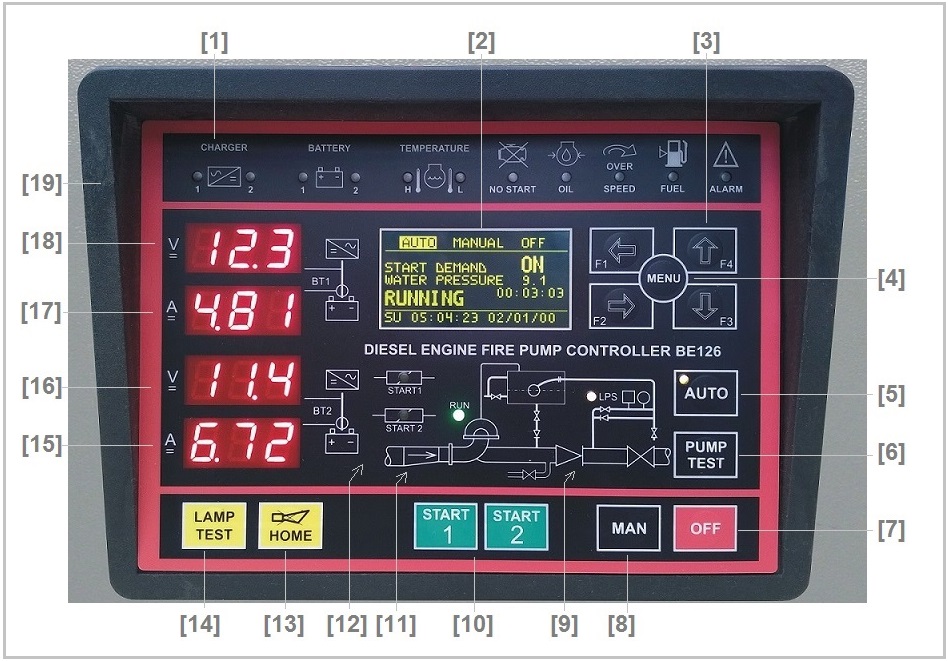
[7] OFF PUSH BUTTON [8] MAN PUSH THE BUTTON [9] PRESSURE INDICATOR [10] START PUSH BUTTONS [11] ENGINE RUNNING LED [12] START PILOT RELAYS [13] HOME BUTTON [14] LAMP TEST & ALARM SILENCE [15]-[16] [17]-[18] BATTERY 1 INSTRUMENTS
THE NFPA 20 MANUAL MODE
Push the [MAN] button. The display will indicate the message [MANUAL].
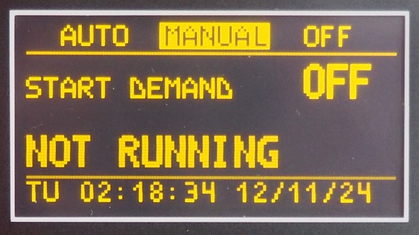
To start the engine using the BATTERY SET 1 push the [START 1] button
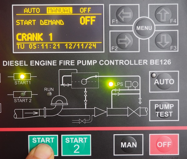
Push the [START 2] button if you want to use the BATTERY SET 2
Push and hold the button until the engine starts. The display will indicate the message [RUNNING] and the green LED ‘RUN’ will turn on. You can program a [CRANK DELAY] and [PREGLOW] before activating the starter motor. The Be126 terminates the crank according to your settings. In NFPA applications, the Be126 ignores the [PREGLOW] setting. Push the [ ↓ ] button to open the engine instruments page. When the battery voltage drops below 6 volts, the Be126 may reset the software. The controller will restart in the AUTO mode.
STOPPING THE ENGINE IN THE MANUAL MODE OF OPERATION
To stop the engine you have to push the [OFF] button. The Be126 removes the power to the ‘Fuel Solenoid’ (output JC-8). In case you use an energized to stop solenoid, the Be126 activates the output JC-4 according to [STOP SOLENOID] timing. When you push the [OFF] button, you also enter the OFF mode of operation. The Be126 clears all alarms and resets the system.
An optional way to stop the engine is to enter the AUTO mode of operation. If there is no fire alarm (all sources of start have been returned to normal) the Be126 will shut down the engine after the [STOP DELAY] timing. Please note that factory programming for [STOP DELAY] is OFF (the engine will not stop automatically).
In the NFPA application, you can not program a time lower than 30 minutes.
THE NFPA 20 AUTO MODE
Push the [AUTO] push button until the yellow AUTO indicator illuminates (you can connect a lamp to JB-4 output); the display will indicate the message [AUTO].
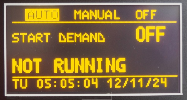
The engine starts when the Be126 detects one of the following conditions:
- the water pressure switch is open (digital input JF-4)
- the water level switch is open (digital input JF-7)
- the water pressure drops below the [START DEMAND] setting (see 19.01 & Input JM-1)
When the Be126 detects a water pressure drop, the yellow indicator >LPS< blinks. The display will switch the message [START DEMAND OFF] to [START DEMAND ON]. The Be126 will initiate the start sequence after a [START DELAY] bypass time (see the [MISCELLANEOUS] menu 21.0.1). Depending on your settings, the engine will run at idle speed or immediately at nominal speed.
When the engine is running, use the display arrows to browse the instruments. If you get lost during navigation, push the [HOME] button: the display will open the ‘System Status Page’. Push the [OFF] button to stop the engine.
We remind you that according to NFPA 20 specifications, only an OVERSPEED condition can shut down the engine. All the other alarms provide only a warning.
The Be126 will periodically test the engine if the scheduler is correctly programmed. The display will indicate the message [TEST SCHEDULER]. After the test, the engine will stop based on your settings. You can analyze all events by browsing the [EVENT HISTORY] menu.
When the Be126 is in the AUTO mode of operation, you can test the automatic system by pushing the [PUMP TEST] button. The Be126 will activate the drain to initiate a test.
To find out more about the AUTO mode of operation, consult Chapter 12 of the NFPA 20 Standard and sections 10.9.7---.13 of the EN 12845 Standard.
THE NFPA 20 TEST MODE
1) Push the [PUMP TEST] button.
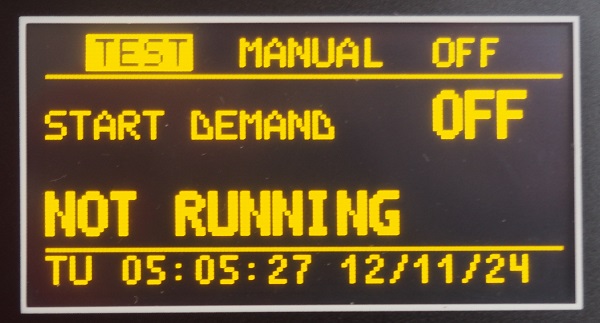
2) The display indicates the message [TEST START].
3) The Be126 activates the DRAIN VALVE (output JB-5) to initiate a test.
4) The Be126 will start the engine when the sensor detects a water pressure drop.
5) The engine will run and eventually stop according to your settings.
(*) Note. If, after a minute time, the pressure fails to drop down, the Be126 will trigger the alarm [TEST START] (see section 21.0.2 to change the alarm delay if necessary).
THE NFPA 20 WEEKLY TEST
The Be126 features a [TEST SCHEDULER] menu that will weekly exercise the diesel engine (see 8.0). You can program a day of the week, hour and minutes to start the engine. You must program in the same day, hour and minutes to stop the engine. At the programmed date & time, the ‘scheduler routine’ will activate the DRAIN VALVE (output JB-5) and will display the message [TEST SCHEDULER]. You can program a [TEST FAILURE WARNING] alarm timeout in case the system will not trigger a start (see the [TEST FAILURE] in section 21.0.2). Once started, the engine will run for the programmed time of the [TEST SCHEDULER] menu. The [EVENT HISTORY] will record all events indicating date & time. The embedded data logger will record the variation of the water pressure (supposing you connected and correctly configured a water pressure transmitter).
We recommend that you consult the chapter 12 of the NFPA 20 Standard.
NFPA 20 FIRE PUMP CONTROLLER HARDWARE OVERVIEW
The Be126 Fire Pump Controllers from Bernini Design are designed to control and monitor 12 or 24-volt, diesel fire pump engines used in NFPA 20 or UNI-EN 12845 compliant fire fighting applications. Firstly, the Be126 is among the most technically advanced diesel engine controllers. Secondly, the Be126 features a state-of-the-art multiprocessor structure providing an embedded water pressure data logger capable of storing up to 31 days of data recording.
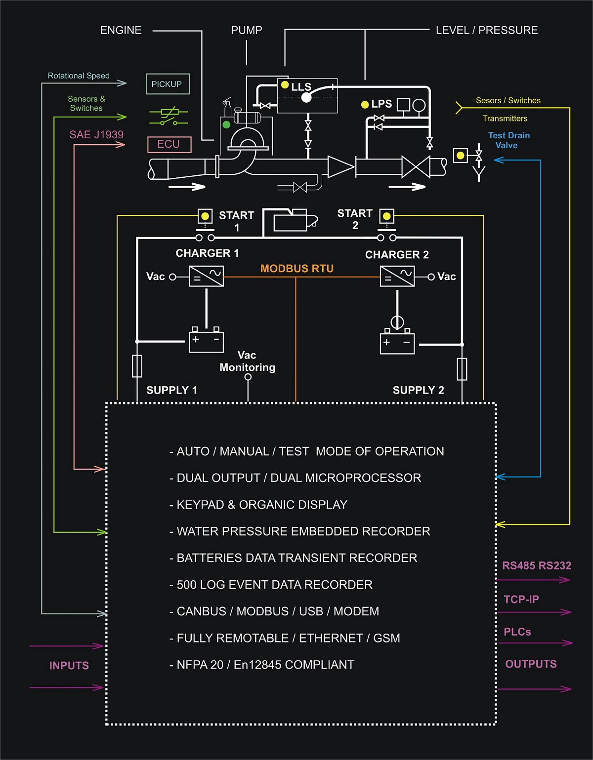 Thirdly, the Be126 interfaces with standard diesel or SAE J1939 compatible engines. Additionally, the Be126 fire pump controller monitors, displays, and records fire pump system information. The Be126 diesel engine fire pump controller is designed to start the diesel engine automatically from water pressure control or non-automatically from manual electric control. Furthermore, this type of diesel engine fire pump controller maintains the full charge on engine starting batteries, monitors engine and system conditions, and initiates a weekly program test of the system. Be126 monitors analogue or digital water pressure or water level transducers. Be126 can provide mathematical calculations over the pressure, providing MIN, MAX, and AVG values. By enabling the Engine Protection Mode software you can use the Be126 controller on a standard diesel engine pump water station. In conclusion, the Be126 controller features RS232 and RS485 serial interfaces that provide ASCII and MODBUS protocols.
This fire fighting system controller's reliability of operation is not adversely affected by dust accumulations, temperature variations, humidity, fungus, or adverse elements. The BE126 is extremely strong and insensitive to vibrations. Its basic structure is made of steel and carbon fibre. A NEMA Type 2 drip-proof is provided with IP54 ingress protection.
TO COMPLY WITH NFPA20 THE CONTROLLER MUST DISPLAY THE VOLTAGE AND CURRENT OF EACH BATTERY. BY USING THE MCBXX BATTERY CHARGER, THE BE126 READS THE CHARGING CURRENT VIA RS485-MODBUS.
NFPA 20 TYPICAL WIRING DIAGRAM
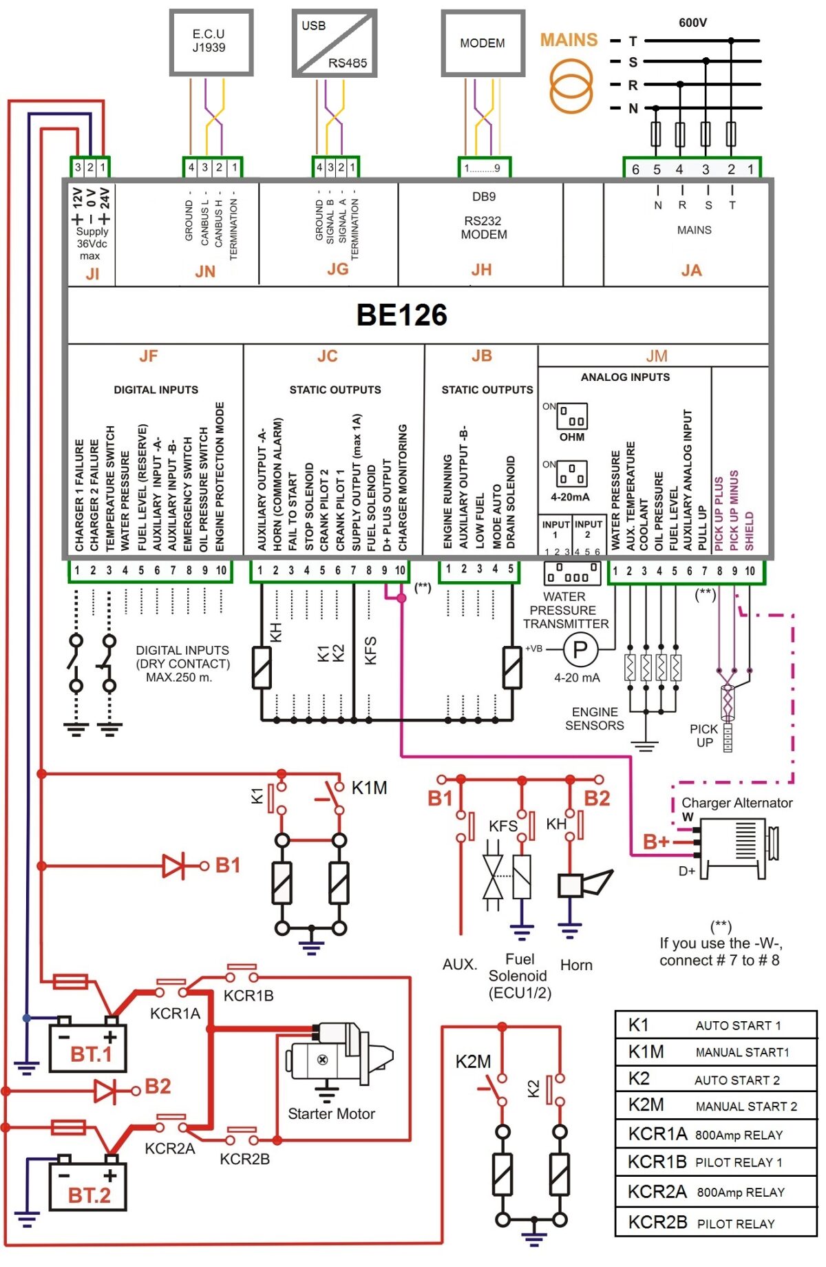
NFPA 20 CONTROLLER DIGITAL INPUTS DESCRIPTION
JF-1 MCB1 FAILURE ALARM. This input detects a failure of the battery charger 1. You can connect the battery charger ‘1’ alarm relay. The alarm triggers when you connect this input to the battery minus.
JF-2 MCB2 FAILURE ALARM. This input detects a failure of the battery charger 2. You can connect the battery charger ‘2’ alarm relay. The alarm triggers when you connect this input to the battery minus.
JF-3 COOLANT TEMPERATURE. This input monitors the Engine Coolant Temperature Switch. The alarm triggers when you connect this input to the battery minus. The Be126 DOES NOT shut down the engine.
JF-4 WATER PRESSURE. This Input detects the loss of water pressure in the firefighting system. The alarm triggers when Be126 detects an open circuit. The input connected to the battery minus holds the Be126 on standby (the WATER PRESSURE is normal).
JF-5 FUEL RESERVE SWITCH. This input monitors the Fuel Level switch. The Be126 provides a warning when you connect this input to the battery minus. According to NFPA20 requirements, you must set up the level switch trigger point.
JF-6 MANUAL TEST SWITCH. Connect here the manual start button to test the engine.
JF-7 WATER RESERVOIR LEVEL SWITCH. Input to detect a LOW WATER LEVEL in the system. The alarm triggers when Be126 detects an open circuit. The input connected to the battery minus holds the BE126 on standby (WATER LEVEL is OK). You can connect here any switch or device able to detect the presence of fire as well. It works in a logical ‘AND’ with input JF-4 providing a safety redundancy. Once Be126 detects one of the inputs open, it triggers the start sequence. Wire the terminal to the battery minus when the function is not used.
JF-8 EMERGENCY SWITCH SWITCH. You can connect this input to the MUSHROOM emergency switch. The Be126 triggers the alarm when you connect the input to the battery minus (active ‘LOW’ input). It should not be used in NFPA applications.
JF-9 OIL PRESSURE SWITCH. This input monitors the Low Oil Pressure Switch status. The Be126 triggers a low oil pressure alarm when a continuity to battery minus is detected. The Be126 does not shut down the engine.
JF-10 OVERSPEED SWITCH. Although Be126 features overspeed detection from a pick-up, you can connect an external engine speed relay.
NFPA 20 CONTROLLER ANALOG INPUTS DESCRIPTION
JM-1 WATER PRESSURE This input accepts a 0-10V or 4-20mA pressure transmitter. The Be126 allows for a wide range of adjustments and calibration. Consult section 19.0 to set up the pressure measurement.
JM-2 AUXILIARY TEMPERATURE This input monitors an auxiliary temperature transmitter. See section [AUXILIARY °C] submenu to set an alarm (see section 20.0). You can choose a 4-20mA or 0-10V transmitter.
JM-3 COOLANT TEMPERATURE This input monitors the coolant engine temperature. To set or adjust the response curve, see section 18.0 ([ENGINE TEMPERATURE] ).
The allowed range for the sensor is 0-1000 OHM.
JM-4 ENGINE OIL PRESSURE This input monitors the engine Oil Pressure. See section 17.0 ([OIL PRESSURE]) to set an alarm or to adjust the sensor response curve.
The allowed range for the sensor: 0-1000 OHM.
JM-5 FUEL LEVEL This input monitors the Fuel Level. See section 16.0 ([TANK FUEL LEVEL] ) to set an alarm or to adjust the response curve. The allowed range for the sensor is 0-1000 OHM.
JM-6 RESERVED NO CONNECTION
JM-7 RESERVED NO CONNECTION
JM-8 PICKUP (A) / JM-9 PICKUP (B) / JM-10 CABLE SHIELD
You can connect a magnetic pickup to detect the rotational speed. You are required to set the number of teeth in the parameter [PICKUP/W RATIO] (see the [ROTATIONAL SPEED] menu in the user manual section 14.0).
NFPA 20 CONTROLLER OUTPUTS DESCRIPTION
NFPA 20 ALARM MONITORING
The Be126 manages alarms according to the NFPA 20 guidance. The graphic display indicates each alarm with a full description. The alarm page is stored in a 'NON VOLATILE' memory with full details. Some alarms may shut down the engine.
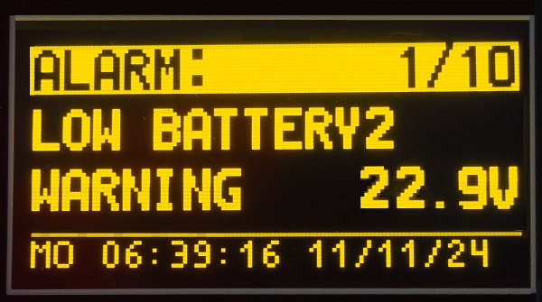 The above picture displays a warning alarm about battery 2 failure on a 24V system. The Be126 controls up to 50 alarms about the engine, pump, sensors, settings, memory failure, clock failure, and miscellaneous system alarms.
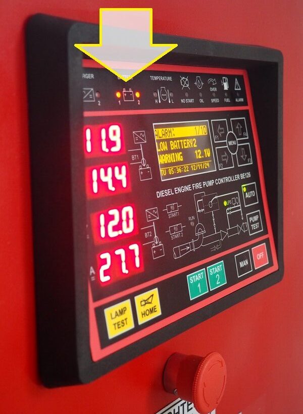
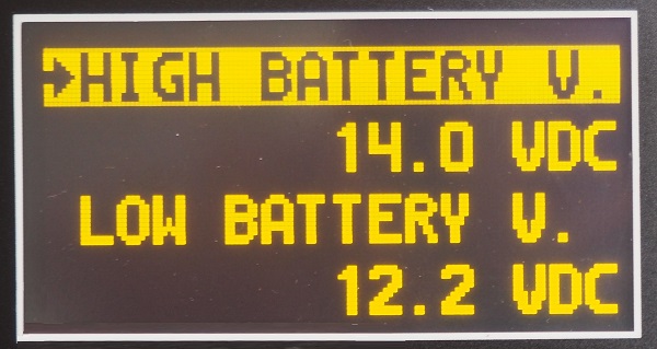
The above picture displays a warning alarm about battery failure on a 12V system. The below image shows an example of HIGH battery and LOW battery setup.
MODBUS BASED NFPA20
BATTERY CHARGERS
Use two independent sets of batteries. Each battery must feature its own battery charger. The Be126 displays voltages and currents via RS485 serial connections.
- MODBUS via RS485, Alarm Relay (dry contacts)
- Operating Temperature Range: -30/+70 deg. Celsius
- Current limited, it will only output the rated current
- Boost Mode push button, Current setting via Trimpot
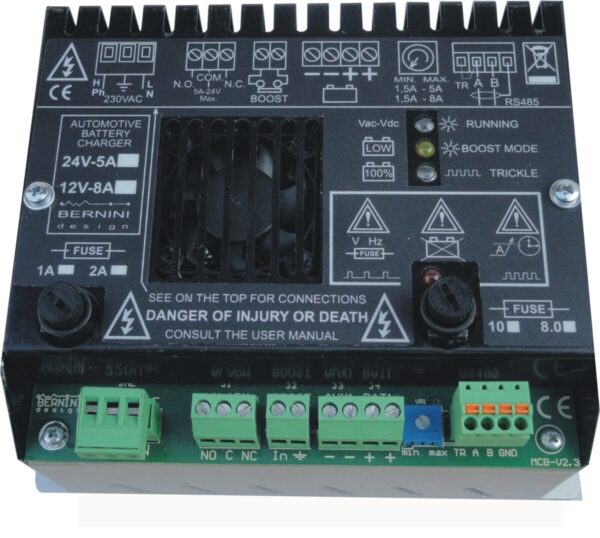
The MCB family of automatic intelligent battery chargers is designed for industrial-automotive applications in harsh environments. Installing the MCB battery chargers, you can make reliable control panels for firefighting protection. The MCB battery chargers feature high-performance components and corrosion-resistant anodized aluminium housings. In addition, the MCB chargers are microcontroller-based especially designed for NFPA110 & NFPA20 applications. The MCB battery chargers comply with UL1236 and NFPA-20 regulations.
MCBXX HIGH-RELIABILITY BATTERY CHARGERS
KEY FEATURES
20 YEARS CONTINUOUS DUTY 24h/24h BY DESIGN
Microprocessor-based, 4 LED indicators
Removable connectors (M/F) & two fuses on the front
Over-voltage/Current, Over-Temperature protections
Ideal for industrial NFPA 20 panels
Boost charge time out, fault Battery detection
Complies with DIN41773, Reverse Battery Protection
ZONA INDUSTRIALE
OSTIGLIA - ITALY
bernini@bernini-design.com
+39 335 70 77 148

