ATS Controller Tutorial
Mode Of Operation
Why and when to install the Be242
Making an ATS panel
Connecting the electric power
The Universal interface relay board
Purchase the ATS controller
Download the installation manual
The safest auto mode of operation.
Simply push the [AUTO] push button of the ATS controller until the green LED illuminates. The engine starts and stops following an excellent software.
The Contactor of the "PRIMARY SOURCE" (KM) opens after the BREAKER timing. After the warm-up time, if the voltage and frequency are within the settings, the circuit breaker of the "SECONDARY SOURCE" (KG) will close.
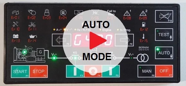 If the UTILITY POWER is restored, the KG will open. The KM will close following a programmed changeover timing. The Engine will stop after cooling downtime. If the engine shuts down, the KM closes independently of the "UTILITY POWER" status if the [P.48] is [ON] (NFPA-110 mode); otherwise, the KM will close only if the UTILITY POWER is within programmed settings. In AUTO mode, the BE242 will periodically test the engine. You must set parameters [P.41] and [P.42]. During this test, the AUTO mode green LED will continue to blink. The Be242 controller starts and stops the engine according to programmed inputs.
A "user-frindly" manual mode of operation.
All functions are intuitive. High-luminosity indicators guide you through each step in activating a contactor or starting and stopping the generator after (or not) a cooling-down time.
The MANUAL mode allows manual control of the engine and circuit breakers. Push the [MAN] push button to select the MANUAL mode. Push the [START] push button of the ATS controller until the engine starts; the display indicates the message [. . . .] during the starting attempts or [! ! ! !] if preheat has been programmed.
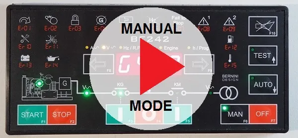 To transfer the Load to "UTILITY POWER", push the [I] (KM) push button (the [KG] will open). Push the [O] push button to open a Contactor. In manual mode, the CHANGEOVER timer lasts one second. The membrane push buttons are rated for an industrial environment and designed to last decades.
Semplicity in programming
Despite the ATS controller is delivered with defaults that meet all general-purpose applications, you can adapt the controller to your miscellaneous needs.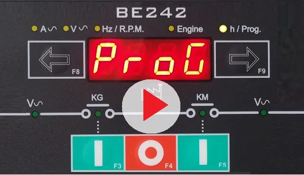
The Be242 ATS controller features over 50 adjustable settings, including various Input/Output options. In other words, you can adapt the controller to old-fashioned or second-hand engines. You do not need external tools for programming.
As you can see from the following picture, the electronics, critical parts of the ATS controller, are outside the panel, far away from the powerful noise generated by electrical components.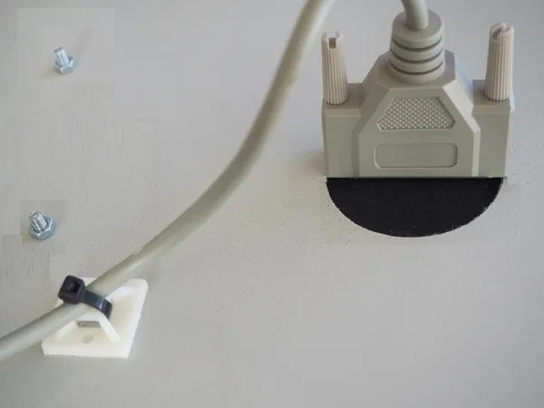
Build Your Own ATS Panel
A traditional ATS controller needs as many meters of cables, as many connections and as many accessories. The Be242 controller is made of two parts. You will change the way you make ATS panels. On the backplane, you install the interface relay board. It will be easy to connect the engine auxiliary circuits. You will benefit from the following features
FUEL SOLENOID RELAY
STOP SOLENOID RELAY
START SOLENOID RELAY
2 CONFIGURABLE RELAYS
2 CONFIGURABLE DIGITAL INPUTS
3-PHASE 600V INPUT GENERATOR
3-PHASE 600V INPUT UTILITY POWER
8Amp KM DRIVE RELAY
8Amp KM DRIVE RELAY
3X5Amp CT INPUTS
2xfuses FOR THE COILS
BELT ALTERNATOR I/O MONITOR
OVER 100 ADJUSTABLE SETTINGS
20 mm-THICK ATS CONTROLLER

You will fix the controller on the door of the ATS panel by making 4 holes. You will make a round hole for the interconnection cable we supplied. No square hole is required. It is a 5-minute job. The BE242 controller will benefit from the metal door plate shielding effect.
ATS CONTROLLER INSTALLATION MANUAL
Thanks to the ATS cable, you can no longer wire connections to the rear door panel.
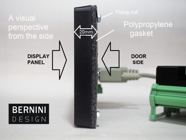
The relay board includes auxiliary relays and short-circuit-proof components. To make a professional Automatic Transfer Switch panel, you only require a metal or plastic cabinet, a battery charger, current transformers, and contractors. The configurable INPUT-OUTPUT options allow you to choose the best solution.
Despite its square shape, the BE242 controller needs only a round hole for the interconnection cable and emergency switch.
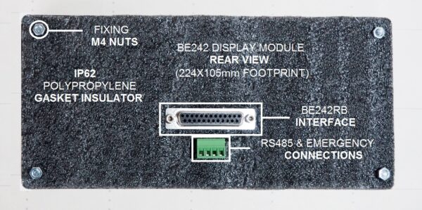
ATS Controller Interface Board Tutorial
The controller on the front door features an ATS interface cable. This is connected to the Relay Interface Board. The Be242RB module features all removable connectors needed to interface with the engine, the generator, the mains, and miscellaneous input-output lines.
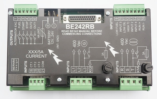
The label on the top of the module indicates all functions. The board is supplied from the engine's battery via automotive blade terminals. The following sections will explain all the details.
INTERFACE BOARD DIMENSIONS
This ATS controller board interface features a metallic cover. Electric noise generated by the changeover will not affect the accuracy of the electrical measurements.
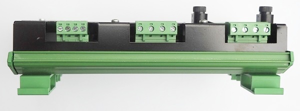
This ATS controller extension board includes 7 relays committed to driving the engine auxiliary circuits and the changeover coils.
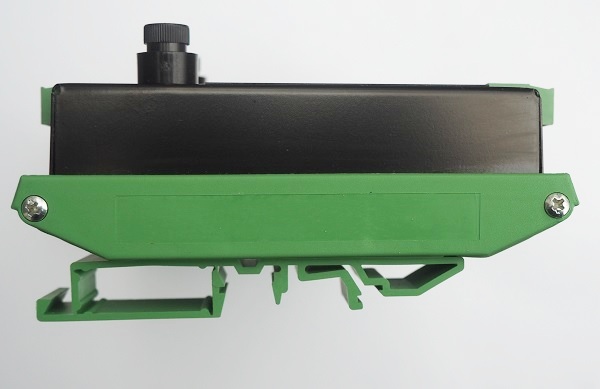
The board features electronic fuses and glass fuses to protect the coils of the changeover. The installation of this board drastically reduces the component count of your bill of materials. Not to mention the time you save assembling this item. The total weight is about 500 grams.
ATS CONTROLLER INPUTS
The ATS controller interfaces with all kinds of switches. The Be242RB offer 3 fully configurable inputs. For each input, you can choose one of the 28 options. By default, input 3 is configured to "REMOTE ENGINE TEST INPUT".
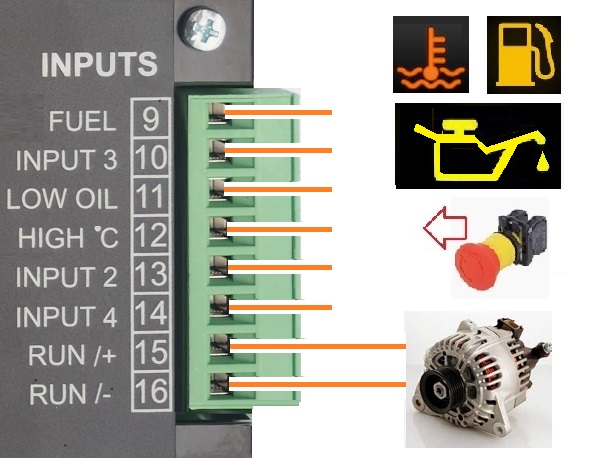
In the same way, input 2 is configured as "REMOTE LOCK INPUT", while input 4 is configured as "MAINS SIMULATED INPUT". All inputs are protected against overvoltages, AC voltage up to 50V, and reverse polarity.
|
ATS Controller Input Options List |
|||||
| Option | Option | ||||
| [ 0 ] | Off: disables the input | [ 14 ] | Generator simulation ON | ||
| [ 1 ] | Immediate Stop | [ 15 ] | Mains Simulated ON | ||
| [ 2 ] | Bypass and Stop | [ 16 ] | Front panel LEDs test | ||
| [ 3 ] | Cooling and Stop | [ 17 ] | Horn silence | ||
| [ 4 ] | Bypass+Cooling and Stop | [ 18 ] | Display Right Push button | ||
| [ 5 ] | Warning only (^) | [ 19 ] | Display Left Push button | ||
| [ 6 ] | Bypass and Warning | [ 20 ] | Overload Input Warning | ||
| [ 7 ] | Remote Manual Mode (^^) | [ 21 ] | Overload Input Shutdown | ||
| [ 8 ] | Remote Auto Mode (^^) | [ 22 ] | KG Forced closed | ||
| [ 9 ] | Remote Off Mode (^^) | [ 23 ] | KM Forced closed | ||
| [ 10 ] | Remote Engine Test | [ 24 ] | KG LED Feedback | ||
| [ 11 ] | Remote Generator Test | [ 25 ] | KM LED Feedback | ||
| [ 12 ] | Ejp function | [ 26 ] | Idle Engine | ||
| [ 13 ] | Remote LOCK | [ 27 ] | Manual START push button | ||
| [ 28 ]
|
Manual STOP push button | ||||
ATS CONTROLLER OUTPUTS
The ATS controller DC outputs feature short-circuit-proof relays. The outputs are designed for driving automotive relays. The total current delivered by the outputs may not exceed 4 amps. Over this current, the ATS controller triggers the output short-circuit protection.
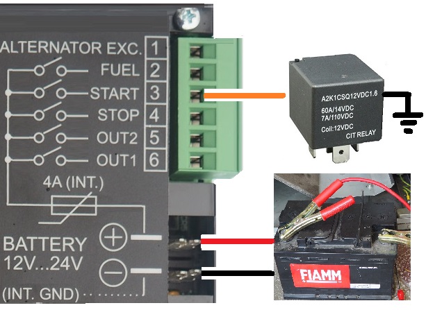
The OUTPUT 1 is programmed by default as "ALARM OUTPUT". You can connect a sound alarm. The OUTPUT 2 is programmed by default as "PREGLOW". You may install a pilot relay to start a diesel engine.
|
ATS Controller Output Options Table |
| Option & description | Option & description | ||
| [ 0 ] | Output is disabled | [32] | Alarm from Input 2: Shutdown/Warning |
| [ 1 ] | Under Frequency Shutdown | [33] | Alarm from Input 3: Shutdown/Warning |
| [ 2 ] | Over Frequency Shutdown | [34] | Alarm from Input 4: Shutdown/Warning |
| [ 3 ] | Over Current Shutdown | [35] | NOT USED |
| [ 4 ] | Over Current Warning | [36] | NOT USED |
| [ 5 ] | Overload Warning or Shutdown (^^^) | [37] | Cumulative Alternator Alarms |
| [ 6 ] | Over-Voltage Shutdown | [38] | Common Fuel Alarms |
| [ 7 ] | Under Voltage Shutdown | [39] | HORN |
| [ 8 ] | Alternator Failure Shutdown | [40] | Crank Delay (Start Warning) |
| [ 9 ] | NOT USED | [41] | Presence of Nominal Mains Parameters |
| [10] | Low Oil Pressure Shutdown | [42] | Mains Failure Timing |
| [11] | NOT USED | [43] | Mains Restore Timing |
| [12] | NOT USED | [44] | KG Status |
| [13] | Temperature Switch Shutdown | [45] | KM Status |
| [14] | NOT USED | [46] | Pre-glow MODE 1/2/3/4 |
| [15] | Low Battery Voltage Warning | [47] | NOT USED |
| [16] | High Battery Voltage Warning | [48] | RENT<48h |
| [17] | Low Fuel Shutdown (switch) | [49] | RENT=0h (Expired) |
| [18] | NOT USED | [50] | Engine Running Status |
| [19] | Fuel Reserve Warning (switch) | [51] | Presence of Nominal Generator Voltage |
| [20] | NOT USED | [52] | Be242 in OFF MODE (Status) |
| [21] | NOT USED | [53] | Be242 in MANUAL MODE (Status) |
| [22] | Emergency Stop Shutdown (Er08) | [54] | Be242 in AUTO MODE (Status) |
| [23] | Stop Push button Used in AUTO (Er09) | [55] | Be242 in TEST MODE (Status) |
| [24] | Maintenance SERVICE 1 (Er10) | [56] | Be242 in LOCK MODE (Status) |
| [25] | Maintenance SERVICE 2 (Er10) | [57] | Be242 runs the Automatic Periodic Test |
| [26] | Maintenance SERVICE 3 (Er10) | [58] | Cooling Timing |
| [27] | Engine Belt Breakdown Shutdown | [59] | Warm-up Timing |
| [28] | Fail To START Shutdown | [60] | Cycling mode (Logical OR of engine running and stop solenoid) |
| [29] | Fail To STOP Shutdown | [61] | Start Pilot repeat output (it repeats the crank output terminal #9) |
| [30] | Idle Speed (see section 16.60) | - | -- |
| [31] | NOT USED | - | -- |
VOLTAGE MEASUREMENTS
The ATS controller directly interfaces with GENERATORS and UTILITY POWER LINES up to 600VAC. The fuses indicated in the picture are mandatory. These fuses (or a circuit breaker as an option) protect the wires in case of a direct short-circuit.
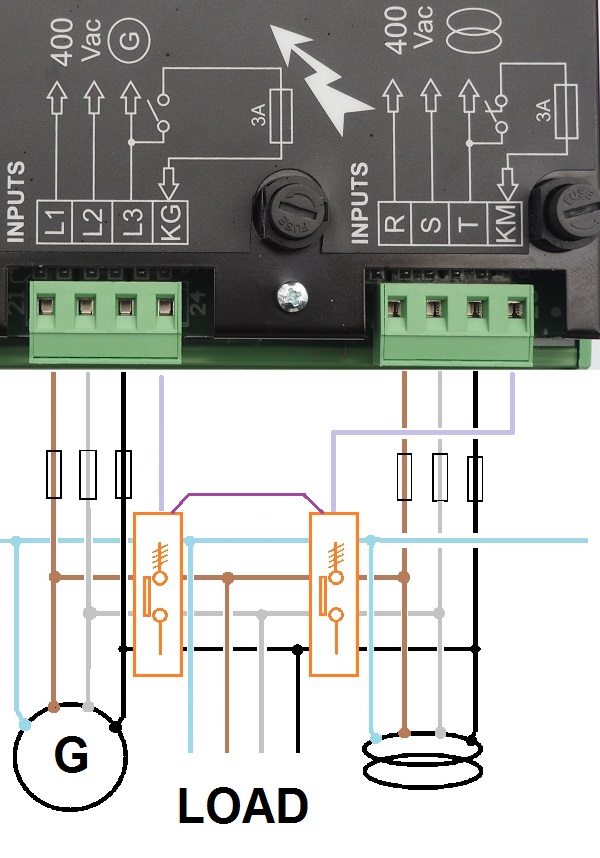
You will find more details about contactors or motorised switches driving in our tutorial:
CURRENT MEASUREMENTS
We always recommend installing CURRENT TRANSFORMERS of a suitable size. You will have a precise measurement of the current that flows in your LOAD, and you can set warnings and shutdowns in case of an OVERLOAD.
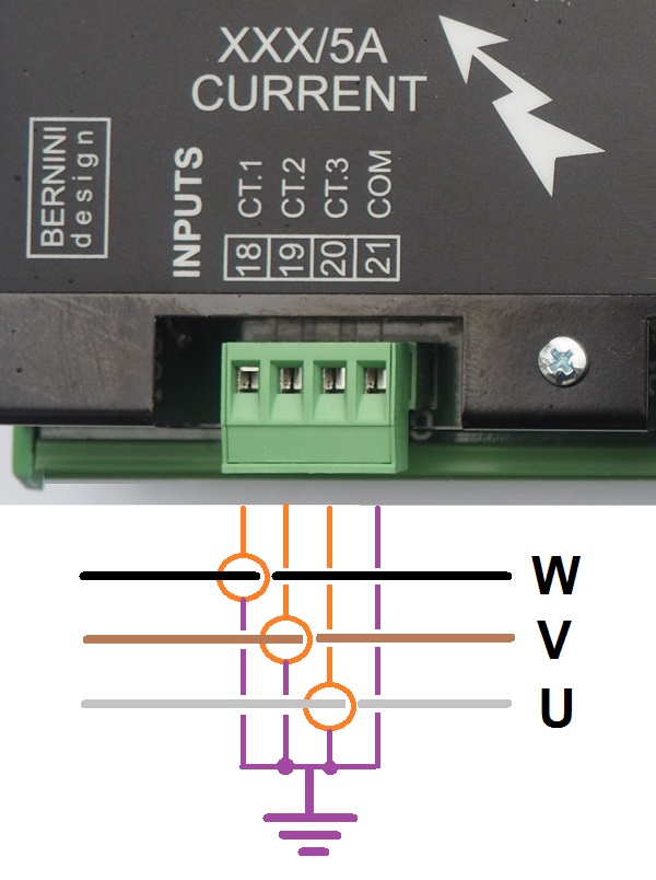
The ATS controller interfaces with current transformers from 50/5A up to 1000/5A
ATS Controller Alarms Monitoring Overview
The ATS controller features Shutdowns (the engine stops) and Warnings (the engine will continue to run) and provides:
- - a general indication of alarm presence using the message [ALAr.] on the display
- - 2 configurable outputs for specific alarm indications with more than 40 options
- - symbols on the front panel to indicate the most important alarms
- - display messages indicating warnings and shutdowns
- - a push button to silence the Horn ([ACK-F10])
Terminal #6 is pre-configured for HORN output (Option 39). A HORN should be externally provided. To silence the HORN, push the [ACK-F10] push button or wait for the [P.50] to expire (see section 7.05). If the [P.50] is set to [OFF], the only way to silence the Horn is by using the [ACK-F10] push button.
| Display | Description | Display | Description |
| [Er.01] | Over Frequency Shutdown | [Er. 14] | Low Oil Pressure Shutdown |
| [Er.02] | Engine Belt Break Shutdown | [Er. 15] | Temperature Switch Shutdown |
| [Er.03] | Remote LOCK Shutdown | [Hi-C] | Overcurrent Shutdown or Warning |
| [Er.04] | Alternator Failure Shutdown | [Hi-U] | Over Voltage Shutdown (see [P.10]) |
| [Er.05] | Overload Warning | [Lo-U] | Under Voltage Shutdown (see [P.09]) |
| [Er.05] | Overload Shutdown | [InP.2] | Input 2 Shutdown / Warning (see 7.07) |
| [Er.06] | Under Frequency Shutdown (see [P.11]) | ||
| [Er.07] | Fail To STOP Shutdown | [InP.3] | Input 3 Shutdown / Warning (see 7.07) |
| [Er.08] | Emergency Shutdown | [InP.4] | Input 4 Shutdown / Warning (see 7.07) |
| [Er.09] | Emergency Shutdown triggered by the Front Panel (Stop or [0] push button) | [FUEL] | Low Fuel level warning |
| [Er.10] | Maintenance SERVICE warning | [rEnt] | The rental contract is going to expire (48 hours remaining). Push [←F8] to display the value. |
| [Er.11] | Fail To START Shutdown | [FAIL] | There is an internal failure or memory error in the BE242 controller |
| [Er.12] | Low Fuel Shutdown | [Er. 13] | Battery Voltage Alarm. Push [←F8] to display the value. |
To browse the alarm memory, push the [→F9] push button. To display alarm details, push the [←F8] push button. To clear the alarm from the panel, remove the cause of the alarm and then press the [OFF] push button. Table 4.10 in section 4.0 indicates all alarms.
ATS Controller Special Application Wiring Diagrams Collection
The "SECONDARY SOURCE" or "EMERGENCY SOURCE" is usually a diesel generator. The ATS panel connects the LOAD via the KG. This is possible only when the "PRIMARY SOURCE" (in this case, the "UTILITY POWER") is isolated using the KM. The KM auxiliary contacts are closed when the KM is open. In this way, the ATS controller supplies the KG coil. When switching the LOAD to the "PRIMARY SOURCE", the Be242 add a programmable DEAD-TIME. This will avoid sparks over voltages. and overcurrents when the LOAD is highly inductive. This is the case with big electric motors. In other words, before energising a heavy LOAD, the Be242 controller waits for a while. Set the dead time between two and ten seconds.
CLICK ON DIAGRAM, OPEN HD EXPLANATION
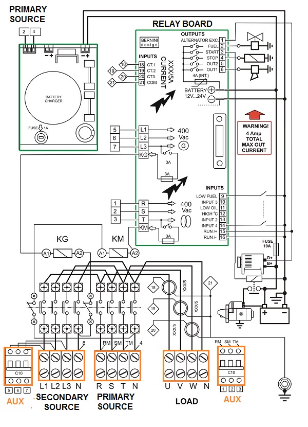
UTILITY POWER-LOAD The utility power is connected to the LOAD via the KM contactor. This output energises the KM contactor. The KG closes its auxiliary contact when it is open. In this way, the neutral line supplies the KM coil. The relay output that drives the KM output features normally closed contacts. By doing so, the ATS controller gives priority to UTILITY POWER in case the ATS controller is damaged or without a supply. The user will not suffer unexpected power failures if the UTILITY POWER is healthy. The ATS controller energises the KM output only in the "TRUE UTILITY POWER FAILURE" event. This prevents the panel from supplying the LOAD with improper electrical parameters. Once the KM is open, the auxiliary contacts KM will close. This action will enable the KG to connect the load to the generator.
THE MOTORISED SWITCH-BASED DIAGRAM
The motorised changeover consists of a switch with three positions: "primary source," "OFF," and "secondary source." An electric motor drives the switch to move in each position.
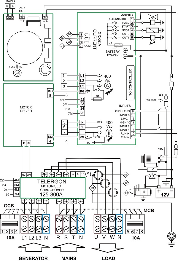
The motorised changeover has several advantages. First, it can manage big currents compared with a contactor changeover. Second, it does not require power to hold the position. Third, it is a cheap and safe solution for high-power switching.
ATS CONTROLLER CONTROLS TWO SEPARATE LOADS
Install the ATS controller to supply two separate loads from a single generator. The generator connects to the load affected by the power outage. This application is typical in private houses. Two houses' power outages can be resolved by investing in a single generator. You must make two ATS panels of a suitable size.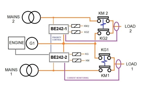
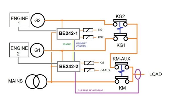
ATS CONTROLLER IN A DUAL GENERATOR SYSTEM
The following wiring diagram presents the basic connections of a dual-generator ATS controller configuration. With Be242, you can connect two generators as an emergency standby to one single load. The BREAK-BEFORE-MAKE configuration is mandatory for the protection of the load. In case of a prolonged outage, you can set up ENGINE 1 as a master. In case of starting failure, the second engine will start. The generator will supply the load. You are required to include the ATS controllers and transfer switches in the same cabinet.
SETTING UP THE ATS CONTROLLER
The Be242 is user-friendly. The installation manual will help you install the panel. The ATS controller features default settings for a 400V 3-phase system. You can program the ATS controller on-site in a few minutes. You can arrange a dual-set configuration or a dual-load configuration. The ATS controller accepts single or three-phase voltage for the utility power and generator. You can choose single-phase or three-phase configurations. To drive the motor of the transfer switch, connect the KM and KG outputs as indicated in the wiring diagram. The battery supplies the ATS controller's electronic circuits. You can use the ATS controller for up to 1000kVA electrical systems.
ATS CONTROLLER SPECIFICATIONS
DC Supply: 5.5/30Vdc, 50/150mA
Protection: 500mA thermal fuse
Dimensions: 194 X 146 X 205
Panel Cut-out: Round 60mm
Operating temperature: -30 to +70 deg C
Humidity range: 8% up to 90%
Weight: 300 grams
Meets ECC 89/336, 89/392, 73/23, 93/68, IEC 68-2-6
Certification: CE
Display: 4 digits solid state
LED Indicators for all functions
12 Silver-Membrane-Type 100.000 actions life
Over 60 programmable adjustable settings
THE ATS CONTROLLER RELAY BOARD INTERFACE
Supply Voltage: 5.5-30Vdc, 50-150mA
Protection: internal 3A thermal fuse
Dimensions: 210 X 150 X 80 (mm)
Installation: DIN-RAIL
Temperature: -30 deg C up to +70 deg C.
Humidity: 5% up to 90%
Weight: 600 grams
Metts ECC 89/336, 89/392, 73/23, 93/68.
Certification: CE
DC Relay Outputs: 3A 30VDC.
AC Relay Outputs: 8Amp 250V AC
Output Fuses: 2Amp
Connectors: removable terminal blocks
Operating Vac: up to 600Vac
Overvoltage Voltage: 2KVac
CTs: up to 1000/5Aac