
Generator Low Battery Auto Start Controller: the BE1
By installing the BE1 generator low battery auto start controller, you can easily build a reliable and affordable generator auto-start panel. Learn how to get the most from this auto-start module by adding just two automotive relays, a few terminal blocks, and 2 meters of cable. Follow our complete tutorial to get started!
The BE1 is the solution your generator has been asking for.
The BE1 generator auto-start controller is housed in a robust DIN 96 metal enclosure featuring a high-luminosity 4-digit display and six super-bright LED indicators. This versatile module is suitable for gas, gasoline, and diesel engines, and can interface directly with a flywheel generator or a standard belt-driven charger alternator. Connect any analog sensor to monitor oil pressure, engine temperature, and fuel level, or use a magnetic pickup if your setup requires it.
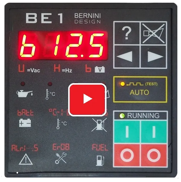
Plus, a high-quality silicone gasket provides dependable IP62 protection against the elements.With standout capabilities like low-battery auto-start, programmable inputs/outputs, and an RS485 serial interface, the BE1 remains uniquely powerful compared to other generator controllers on the market.
The BE1 generator controller price
Free Shipping
199 €
EAN 793541758874
Our "two-pieces" Offer
149 €/each: 298 €
Free Shipping
EAN 793541758874
What is a low-battery auto start generator controller
You can set a LOW BATTERY VOLTAGE threshold (1). The engine will start after a programmable delay (3).
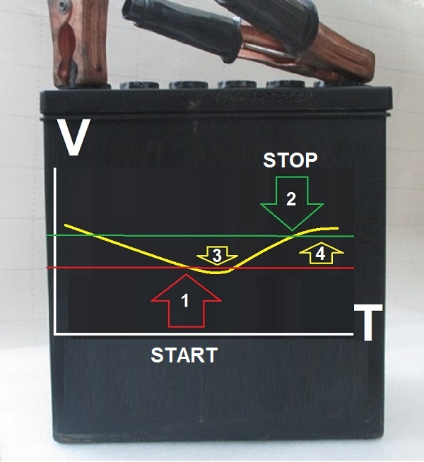
When the battery rises above the HIGH BATTERY VOLTAGE threshold (2), the delay timer (4) will start to count. When the timer (4) will expire, the engine will automatically stop.
LOW BATTERY AUTO START CONTROLLER APPLICATION NOTE
Can you control a generator remotely?
This Generator Auto Start Controller supports the MODBUS protocol. Any MODBUS-compatible device can access the controller. You can download the MODBUS manual which contains all the information.
THE GENERATOR AUTO START CONTROLLER MODBUS REGISTERS
The RS485 interface drives 1000m of twisted cable on a maximum environment of 127 nodes.
The front panel description
The front panel of the BE1 generator auto start is extremely intuitive and thanks to the double set of start-stop buttons, we guarantee the BE1 for at least 2 million start-stop operations. The BE1 is a user-friendly generator GENERATOR AUTO START MODULE and by adding only a few automotive relays you can make an auto-start panel. You can connect analogue or digital sensors.
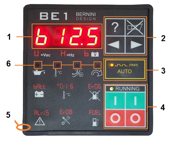
[1] MILITARY-GRADE DISPLAY [2] NAVIGATION BUTTONS [3] AUTO MODE CONTROL [4] MANUAL MODE CONTROL [5] GASKET [6] RED-LED ALARM INDICATORS
You can use BE1 to refurbish the control panel of a gas, gasoline, or diesel engine. The RS485 serial interface supports the MODBUS protocol and the software is free of charge. Thanks to the high-quality gasket the Be1 features IP54 ingress protection. The START/STOP pushbuttons are redundant and you can expect a long life even in harsh environments.
The avionics-grade' display and LED indicators will offer full visibility between -30 to 70 degrees Celsius.
Auto start controller connection tutorial
The BE1 is the perfect choice for a gasoline generator. It interfaces with the Flywheel generator to trigger a crank termination. The Be1 offers two options to stop the gasoline engine: STOP SOLENOID or FUEL SOLENOID.
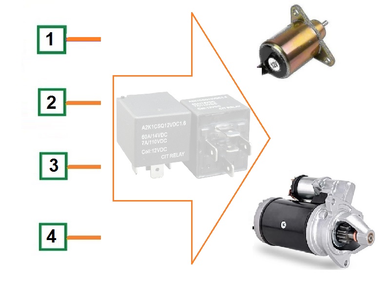
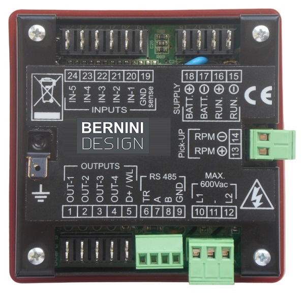 This output energizes when you want to stop the engine. The contact of the relay will close to ground the ignition terminal on the spark generator remote start. You can easily find this terminal because it is normally connected to the STOP switch on the body of the gasoline generator. The engine stops when the spark plug is off. You can adjust the time for STOP SOLENOID. You can also use the FUEL SOLENOID by connecting a relay to the output [1]. The engine runs only when the FUEL SOLENOID output is active. This is an 'ENERGIZED TO RUN' output. The best solution is to use both: STOP SOLENOID & FUEL SOLENOID. The start circuit is quite similar to a diesel engine. Finally, connect the starter pilot relay to the output [2].
Power Supply & Configurable Inputs
Even though all inputs are freely programmable in digital or analogue mode, the BE1 is supplied with factory defaults. The input [4] is set for remote start input in normally closed mode. Connect all switches committed to starting the engine in a logical OR. When at least one input is connected to the ground, the Be1 will instruct the engine to start. When all input switches are open,t the Be1 will instruct the engine to stop.
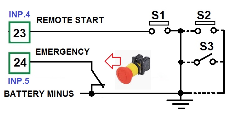
The input [5] is set as normally closed contact. It will trigger the emergency alarm. This input is reserved for the emergency button. All inputs when set in digital mode, only accept dry contacts. It must be isolated from an external source of voltage.
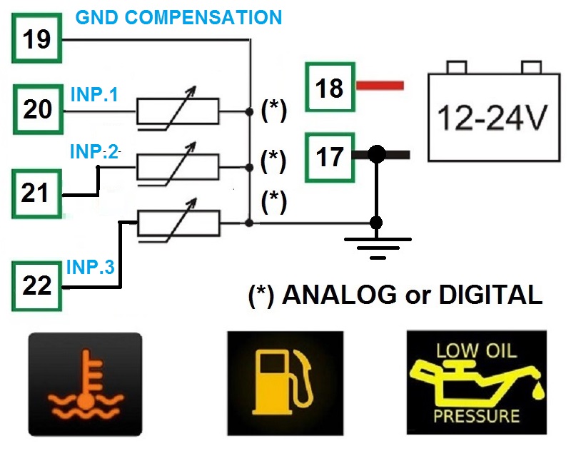
The default programming for INPUT [1] is OIL PRESSURE SWITCH, for INPUT [2] is FUEL LEVEL SWITCH, and for INPUT [3] is ENGINE TEMERATURE SWITCH. Connect dry contact only. Configure the inputs into analogue mode if the engine features analogue sensors. For each input, you can program a 5-point response curve. The power supply must be connected to terminals [17] and [18]. We recommend that you protect the wires with 4 Amps FUSE. The Be1 controller has it own electronic fuse of about 500mA. The Be1 accept 12V or 24V batteries.
The Solid-state Outputs
The BE1 offers four programmable outputs. Each output can be associated with one of the 31 available options. Default programming sets the output for the most common applications, such as fuel solenoid, start, and pre-glow. The outputs are short circuit proof, the logic is negative. The output is designed to drive automotive relays. In other words, you must connect the other side of the relay coil to the battery plus. To avoid electrical noise we always recommend that you use the flywheel diodes.
The RS485 Serial Interface
The RS485 supports the MODBUS protocol. You can monitor the engine, control the alarms, open the Event History, program the Module, and save the programming using a normal computer.
THE BE1 GENERATOR AUTO START MODBUS PROTOCOL
You can extend the RS485 cable up to 1000m. On the same bus, you can connect as many as 24 controllers. We offer solutions for remote monitoring via TCP-IP and GSM.
The Charger Alternator
If you can not connect the flywheel generator, the Be1 features adjustable settings to terminate the crank from the Voltage and frequency of the GENERATOR. You can also connect a pickup to get an accurate reading of the rotational speed. Also in this case do not worry about it. The Be1 can calculate the RPM from the alternator frequency. You only have to set up the number of poles of the alternator. The connection for sensors, analogue or digital, is indicated in the wiring diagram. The terminal [5] supplies excitement current to the alternator. Terminal [15] must be connected to battery minus.
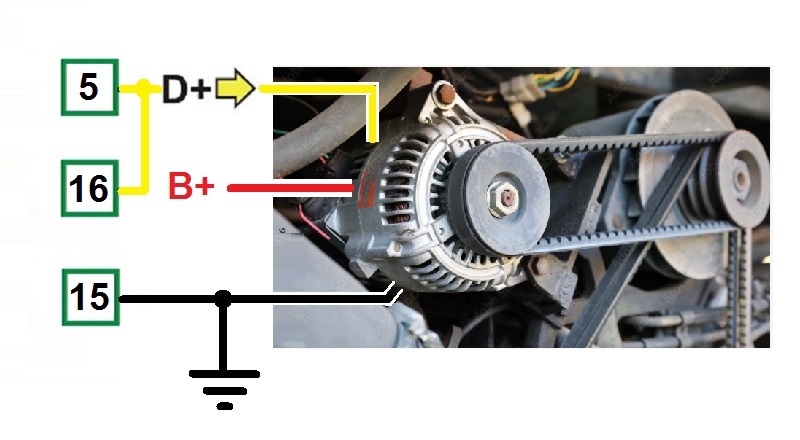
The auto-start generator module automatically terminates the crank when the engine starts running. The BE1 provides an exciting current for the charger alternator. When the engine is not running, the voltage of the terminal D+/WL is 0V (in your car, before starting the engine, the red 'DYNAMO LAMP' turns on).
As soon as the BE1 controller starts the engine, a voltage appears in the D+/WL terminal and when the engine runs normally, the voltage of the D+/WL terminal increases by up to 13-14 V (in your car, having one side of the lamp connected to the battery plus, the red 'DYNAMO LAMP' in the dashboard turns off ). The safest point to terminate the crank is between 6V to 10V.
The Flywell Alternator Monitoring
This is the typical connection for a gasoline engine or a 3000RPM small diesel generator. The wires are floating. For this reason, you must not connect the terminal [5]. The principle of detecting an engine's running status is similar to a belt alternator.
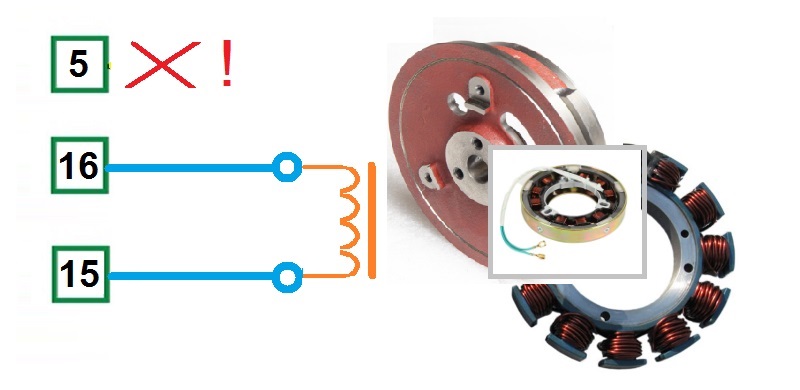
The display indicates the average voltage supplied by the flywheel alternator when the engine runs at a nominal rotational speed.
Specifications
Battery supply voltage: 5.5Vdc to 36Vdc. Supply current: 10 mA to 80 mA.
Inputs: digital (switch) or analogue (0-1000 OHM).
Dimensions: 96X96X 47(mm). Panel Cut-out: 91mm X 91mm.
Ingress protection: IP65. Outputs: 300mA, NPN short circuit proof.
Operating temperature range: -30 deg C up to +70 deg C.
Humidity range: 5% up to 95% non-condensing.
Weight: 350 gr., Vibration: 40mm/sec.
Pick-up Input: Voltage input: 2 - 60Vac; 0-10KHz
Generator Monitoring: Operating up to 600Vac.
Accuracy: +/- 1,5%. Frequency: 20-70Hz
The Manual Mode
A) - Push one of the [ I ] push buttons until the display indicates the message [MAn] and all LEDs illuminate; release the button.
B) - Push one of the [ I ] push buttons until the engine starts. When the engine runs, the green LED 'START-ON' will illuminate.
C) - To stop the engine, push the [ O ] push button until the [StOP] message appears on display.
If the engine has already stopped, it is possible to cancel the STOP sequence by pressing the [ O ] push button. Push [ O ] when the engine is not running if you want to shut down the panel.
The Auto Mode
Push the [AUTO] push button until the yellow LED 'AUTO' on the button illuminates. The engine starts when you activate the input configured as 'Generator Remote Start Input'. Deactivate the 'Generator Remote Start input' to stop the engine. In the AUTO mode of operation, the Be-1 will periodically test the engine if you properly programmed the scheduler or the so-called 'Periodic Auto Start'. During this test, the yellow LED AUTO will continue to blink.
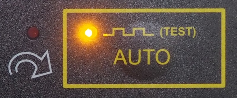
The Be1 controller can start the engine when the battery is low only in Auto mode. You must set the low battery voltage threshold and high battery voltage stop threshold. After configuring the output, you must connect this output to the remote start input.
The AUTO mode of operation is stored in a 'NON VOLATILE MEMORY'. If you remove and re-apply the DC supply, the Be1 will automatically enter the AUTO mode of operation.
To exit the AUTO mode of operation, push, for a short time, the [AUTO] push-button. The Be1 will enter the MANUAL mode of operation. You can directly push one of the [0] push buttons. In this case, the Be1 will directly enter the OFF mode of operation.
Alarn Monitoring
The Be1 auto-start generator kit features Shutdowns (the engine stops) and Warnings (the engine will continue to run). It informs you about an alarm via:
A) - a general indication of alarm using the message [ALAr.] on the display
B) - 4 configurable outputs with several options for each
C) - 4 LEDs indicating Oil pressure, Temperature, Failure to start, and Over-speed shutdown.
D) - coded display messages about warnings and shutdowns
E) - a [ACK] push button to silence the Horn
To browse the alarm memory push the [→] pushbutton. To display the details of the alarm, push the [? ] push button. To clear the alarm from the panel, remove the cause of the alarm and then press the [ O ] push button.
The History Log
This auto-start kit features an Event History memory of the last 100 shutdowns. To read the contents of the Event History, follow the instructions:
A) – Remove the DC power supply (battery voltage)
B) – Push and hold the [?] pushbutton
C) – Apply the power supply (holding the [?] pushbutton)
D) – Release the [?] pushbutton when the display turns on
E) – The display will indicate the last event via the message [E 01]. Push the [?] push button to display the name of the Event (see table 4.10 in the installation manual)
F) – You can select [E 01] (the last event) up to [E100] (the oldest event) using the [←] and [→] push buttons.
G) – To display the code of the Event, push the [?] pushbutton (see table 4.10 in the installation manual).
It is not possible to cancel the Event History. You are required to cancel all memory (see instructions in the installation manual)
Bernini Design Srl
Zona Industriale
46035
Ostiglia Italy
bernini@bernini-design.com
+393357077148