HOW DOES AMF CONTROLLER WORK
You may find hardware information, especially about the wiring diagram, on the following page
INTRODUCTION
The AMF controller integrates a 3-phase AMF relay and a high-performance generator control system that complies with NFPA110 and CAN/CSA-C282-M89 regulations. It provides visual indication for all parameters and alarms through LEDs and an LCD. This AMF controller features over 200 programmable settings.
AMF CONTROLLER FRONT PANEL LAYOUT
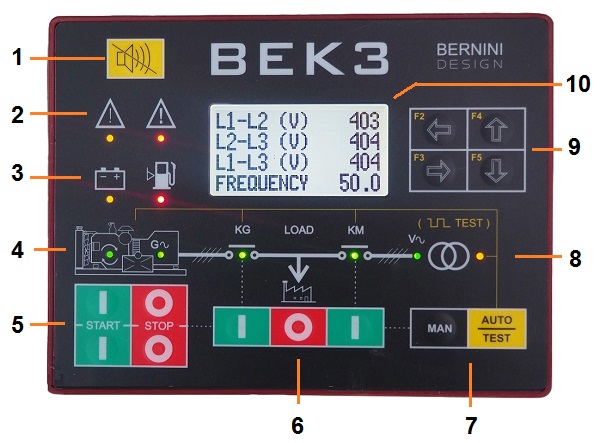
[1] ALARM RESET [2] WARNING and SHUTDOWN indicators [3] BATTERY and LOW FUEL alarms [4] ENGINE RUNNING and GENERATOR PRESENCE indicators [5] ENGINE START-STOP [6] MANUAL CHANGEOVER [7] MODE SELECTION [8] MISCELLANEOUS indicators[9] NAVIGATION buttons[10] LCD
Before diving into the AMF CONTROLLER MANUAL, you may have an overview of what an AMF controller is by browsing the
High voltage is present inside the AMF controller. Operating personnel must not remove the protective cover to avoid electric shock hazards. Do not disconnect the grounding connection. The AMF controller can start the engine at any time. Do not work on equipment, connected to an AMF controller. When servicing the engine, disconnect the battery and battery charger. We recommend that warning signs be placed on equipment indicating the above.
SELECTING A MODE OF OPERATION
The mode of operation is selected by the push buttons [MAN] [AUTO] and [0-STOP]. If the AMF controller was in TEST or AUTO mode before powering down, it enters the AUTO mode when you switch on the power supply. In the other cases, it will enter OFF mode.
MANUAL MODE
Push the [MAN] pushbutton to select the MAN mode. Push one of the [I-START] push buttons until the engine starts. The display shows the ‘ENGINE STATUS PAGE’ with the information about the start sequence. During engine start, the AMF controller turns off the display backlight. The green LED turns on when the engine is running. Press one of the [0-STOP] push buttons to stop the engine. The screen displays the [STOPPING] message. If the engine has already stopped, it is possible to reset the stop sequence by pressing the [0-STOP] pushbutton. Select the MAN mode, start the engine (see 2.2) and wait until the green LED Generator Available turns on. Push the [ KG ] push button to close the generator contactor. To transfer the load back to the Mains wait for the green light indication "MAINS PRESENCE". Push the [ KM ] pushbutton. The KG will open and KM will close after a 2-second changeover delay that overrides your program changeover timer. It works only in AUTO mode. To open a contactor, push the [ O ] pushbutton.
AUTO MODE
!! WARNING !!
The AMF controller can start the engine at any time. When servicing the engine, disconnect the battery and battery charger. We recommend that warning signs be placed on equipment indicating the above.
Push the [AUTO] pushbutton until the yellow LED illuminates. The engine starts when the AMF controller detects a Mains failure (see section 9.01 for settings). The contactor of the Mains opens after the [MAINS BREAKER] timing. After the [WARM UP] time if the voltage and frequency are within the settings, the contactor of the Generator will close (see section 9.02A for the settings). If the Mains is restored, the KG will open. The KM will close following a programmed [KM CHANGEOVER] timing.
The engine will stop after a [ COOL DOWN ] time. Suppose the engine shuts down because of an alarm. In this case, the KM closes independently of the Mains status if the [ NFPA-110 ] mode is active (see section 9.06), otherwise, the KM will close only if the parameters of the Mains are within the programmed settings. In AUTO mode, the AMF controller will periodically test the engine if the periodic test is correctly programmed (section 8.02). During the test, the yellow LED in AUTO mode will continue to blink. In AUTO mode, the Be-K3 can start and stop the engine if a remote control is activated (Table 9.07 options [25] or [26]). To stop the engine choose the MAN mode and push the STOP button.
TEST MODE
Push and hold the [ AUTO ] pushbutton until the yellow LED starts blinking. The AMF controller will start the engine and transfer the load to the Generator only in case of utility power failure if not otherwise programmed by the parameter [ KG TEST CONTROL ] (section 8.03). To exit the TEST mode, push the [ AUTO ] pushbutton shortly or select another mode of operation. If you push the [ 0-STOP ] pushbutton when the AMF controller is in AUTO or TEST, the [LOCAL EMERGENCY] alarm will energize. To clear the alarm, select the OFF mode.
LEDs INDICATORS and LAMP TEST
The table describes the LED functions on the front panel (section 1, figure 1). To test the LEDs, select the OFF mode and push + hold the [←F2] and [F3→] pushbuttons simultaneously. For the NFPA 110 application, program an input with the option [14] and connect an external pushbutton (see application note in section 18.20).
ENGINE TYPE SELECTION
This menu allows you to select the proper ECU from a list of manufacturers. Follow the menu indicated in the display and make a choice.
You can also configure analogue or digital input for conventional engines. The main choices are:
[CONVENTIONAL 1]: #JF4(Oil Pressure) – #JF 5 (Fuel Level) – #JF 6 (Engine Temperature) are configured to work with switches. Do not program settings for Oil-Fuel-Temperature (it can create conflicts).
[CONVENTIONAL 2]: #JF4(Oil Pressure) is configured to work with a switch, #JF5 (Fuel Level) is configured for a sensor and #JF6 (Engine Temperature) is configured to work with a switch.
[CONVENTIONAL 3]: all #JF4-5-6 inputs are configured to work with sensors. You can use a configurable input to connect switches for additional safety (see options [33]-[34]-[35] in Table 9.07).
[CANBUS-J1939...& all models of ECU]: #JF4 is configured for a Low Oil Pressure Switch, #JF5 is configured for a Fuel Level Sensor and #JF6 is configured for Auxiliary Temperature Measurement. You can use a configurable input to connect switches for additional safety (see options [33]-[34]-[35] in Table 9.07).
ENGINE RUNNING DETECTION
The Be-K3 inhibits the starter motor when the engine starts running. When the engine is not running, the voltage in the terminal D+/WL of the charger alternator (input JI-3) is 0V. When the engine starts running, the voltage of the D+/WL terminal increases; the range to disconnect the starter motor is between 6V and 10V. The default parameter of [CRANK VDC] (section 9.03A) is 8.0V. For 24V batteries, we recommend that you set the threshold to 16V. For safe use, ensure the green ENGINE RUNNING LED on the front panel is off during all the starting attempts. The Charger Alternator voltage can be displayed in the Engine menu as indicated in section 5.04. In addition, Be-K3 monitors the generator to disconnect the crank motor. Do not insert a manual switch in series to terminals #JA5-6-7 because it prevents the Be-K3 from detecting an engine running condition from the generator. See the [CRANK VAC] and [CRANK HZ] parameters in section 9.03A.
NOTE: THE ENGINE RUNNING INDICATOR MUST BE LIT WHEN THE ENGINE RUNS. USING THE ENGINE WITHOUT THIS SIGNAL MAY BE DANGEROUS.
ALARMS WARNINGS AND SHUTDOWNS
The Be-K3 features:
- A) – A yellow LED that turns on in case of a warning and a red LED that turns on in case of a shutdown.
- B) - Symbols and LEDs, indicating the alarms of Low Fuel and Low Battery (see Figure 1).
- C) - Configurable Horn output (°) and specific outputs for remote/external repetition of alarms.
- D) - Descriptive messages for alarms with date, time and measurement information.
- E) - Event history capable of recording 200 alarms and events (see section 5.06).
- F) - A pushbutton to silence the Horn ().
(°) The terminal JC-1 is factory-programmed for driving an external HORN. To silence the HORN, push the pushbutton or wait for the [HORN TIMEOUT] to expire (see section 9.06). If the [HORN TIMEOUT] is set to [OFF], the only way to silence the Horn is by using the pushbutton.
- Look at the front panel and take note of LED indicators and messages on display.
- Some alarms shut down the engine after a programmable delay to cool it down. We recommend waiting for the engine to stop completely.
- Push the pushbutton to acknowledge the alarm. Push the [0-STOP]
- Consult the following sections for further information
- Remove the cause of the alarm.
Restart the engine using the proper mode of operation.
NFPA110 MODE, BASIC INFORMATION
To comply with the NFPA110 standard, the ON option in the parameter [ NFPA 110 ] (see section 9.06) needs to be enabled. It is then required to perform the following basic operations:
- Install an external 3-position switch RUN-OFF-AUTO for selecting the mode of operation
- Connect the RUN terminal of the switch to a programmable input with the option [ 26 ] (Remote Genset start)
- Connect the AUTO terminal of the switch to a programmable input with option [ 8 ] (Remote AUTO mode)
- Connect the OFF terminal of the switch to a programmable input with the option [ 9 ] (Remote OFF Mode).
- Connect the other side of the RUN, OFF and AUTO contacts to the battery minus.
- Connect a relay to a Programmable output to drive a lamp. The lamp turns on if the Be-K3 is NOT IN A AUTO MODE (use the normally closed contact of the relay)
- Program the output with the option [54] (See Table 9.08A, Be-K3 in AUTO mode status)
- Program one input with the option [14] (Remote Lamp test) and connect an external pushbutton.
- Consult the NFPA110 documentation and verify if other settings are required.