AMF CONTROLLER WIRING DIAGRAM PDF
The AMF controller directly interfaces with the alternator, the engine, the mains, and ancillary general-purpose input-output.

The AMF controller governs the system, transferring the load to the generator or mains smoothly and with minimal downtime. This AMF controller wiring diagram illustrates the connections that monitor the parameters of the mains and automatically start the engine via relays. This happens after a mains failure programmed delay (seconds, minutes or hours). When the engine is cold, the AMF controller waits for the engine to warm up. The engine will run offload. Once the generator provides the correct frequency and voltage, the controller transfers the load from the mains to the generator. When the mains has been restored, the AMF controller will connect the load back to the mains automatically. After a time delay, the engine is then stopped.
THE AMF CONTROLLER OUTPUTS
You can observe that this AMF controller does not need flywheel diodes. The outputs are static NPN that includes Schottky barrier diodes. The outputs are connected via a removable 8-pin connector, namely [JC]. The outputs are designed to drive automotive relays at 12V or 24.
WHY STATIC OUTPUTS?
The AMF controller works on the topper layer of the automation system. A reliable AMF controller must not include relays. There are many reasons. Firstly, relays are subject to damage. So it is better to have external relays on sockets. In case of failure, you can replace a relay in 5 minutes. You cannot afford to replace an entire AMF controller for the sake of one broken relay. Secondly, you must use a considerable wire gauge in case of high currents. This is not a good idea, considering that the controller is normally placed on the frontal door of the electrical cabinet. Thirdly, using removable relays, you can carry out troubleshooting. e stopped manufacturing AMF controllers with embedded relays in 2001. We had extraordinarily good results.
THE AMF CONTROLLER CONNECTS THE LOAD TO THE MAINS
The KM contactor is committed to connecting the LOAD to the MAINS. The coil of the KM energises via the KG-AUX and KKM relay. The KG-AUX auxiliary contacts are mechanically connected with the KG: the contacts are closed when the KG is open. The KKM relay is the utility power control relay. This relay is OFF when the MAINS is within the settings. The COIL of the KM is supplied via the N and L3 of the MAINS. By using the normally closed contacts, the MAINS to LOAD connection will have priority in case the AMF controller is damaged or without supply. When the MAINS fails, the AMF controller energises the KKM relay. The KKM contacts will open the KM, and the auxiliary contacts KM-AUX will close. This is one of the mandatory conditions to close the KG (the KM must be open in the first place).
THE AMF CONTROLLER CONNECT THE LOAD TO THE GENERATOR
The AMF controller enables the KG via the KKG-PILOT relay. If the KM-AUX contacts, fitted on the body of the utility power contactor (so-called KM), are closed, the KG coil can energise. In other words, the KM-AUX contacts allow the activation of the KG only when the KM is open. The N and L3 of the generator supply the coil of the KG. When switching the generator to MAINS, the user observes a short ‘power outage’. Normally, it is about 2 seconds. This is the typical behaviour of the automatic transfer switch: BREAK-BEFORE-MAKE.
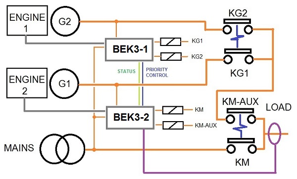
AMF CONTROLLER DUAL GENERATOR SINGLE LOAD CONFIGURATION
With this AMF controller wiring diagram, you can connect two generators as an emergency standby to one load. This is not a parallel configuration. It is a basic BREAK-BEFORE-MAKE configuration. In a prolonged power outage, you can set up one generator as a master. In case of failure, the second one will supply the load.
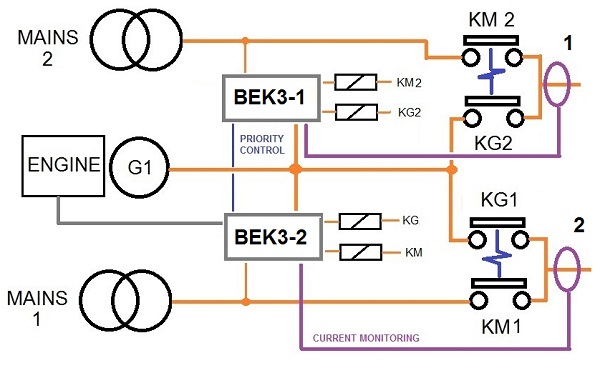
DUAL LOAD WITH A SINGLE GENERATOR
By using this AMF controller wiring diagram, you can connect one generator as an emergency standby to serve both loads. This is not a parallel configuration. The generator will supply the only load that suffers from a utility power condition.