Genset Controller Wiring Diagram
Choosing the proper genset controller wiring diagram is the first step in planning the architecture of your generator control panel. In this guide, we present 3 basic wiring diagrams ordered by performance level and application expectations.
Are You Looking for AMF the Wiring Diagram?
Each wiring diagram is designed to help you achieve the optimal compromise between cost and performance for your installation.
Diagram 1: The Essential Configuration (Be1)
• Best For: Simple backup sets and manual start/stop applications where core engine protections are mandatory without complex network integration.
• Wiring Focus: Direct DC supply routing, basic oil pressure and water temperature sender inputs, and heavy-duty fuel solenoid/starter relay connections.
• Low Battery Start: You can setup the controller to start and stop the engine when battery is too low. This prevents total discrge when the generatore is placed ina remote location.
How Much Be1 Will It Cost?
| Qt. | Unit Price | Total |
| 10 | 89 € | 890 € |
| 25 | 78 € | 1.950 € |
| 50 | 67 € | 3.350 € |
| 100 | 52 € | 5,200 € |
Click to get Full Size
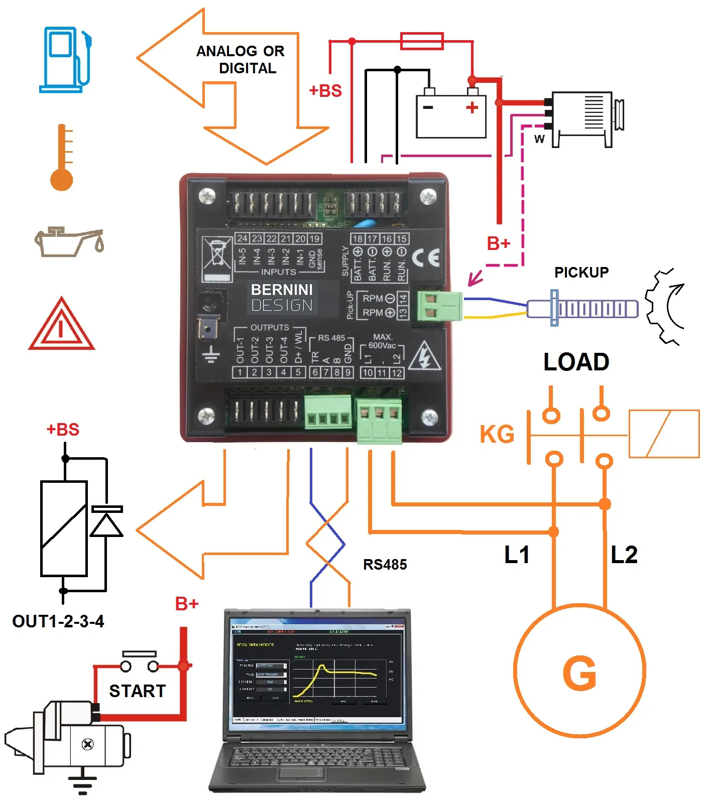
The RS485 serial interface: It supports the ModBus protocol. By using our Modbus Register Handbook, you can have full access to controller settings and functionality.
The Configurable Inputs: default settings feature a digital input for the basic engine protection. You can set up for analogue sensors and set alarm warnings and shutdowns.
The Configurable Inputs: default settings feature the basic need to start and stop a diesel engine. You can set up outputs for gas and gasoline engines. The adjustable outputs feature over 30 options.
Diagram 2: The Standard AMF Configuration (Be24)
A generator control panel wiring based on Be24 is a long-term reliability solution for almost all power generators.
• Best For: Standard residential and light commercial standby panels requiring automatic transfer from utility grid to generator.
• Wiring Focus: Three-phase mains voltage monitoring inputs, automatic changeover contactor interlock wiring, and battery charger integration.
How Much Be24 Will It Cost?
Qt. |
Unit Price |
Total |
12 |
99 € |
1.188 € |
24 |
94 € |
2.256 € |
48 |
84 € |
4.032 € |
96 |
64 € |
6.144 € |
Click to get full size
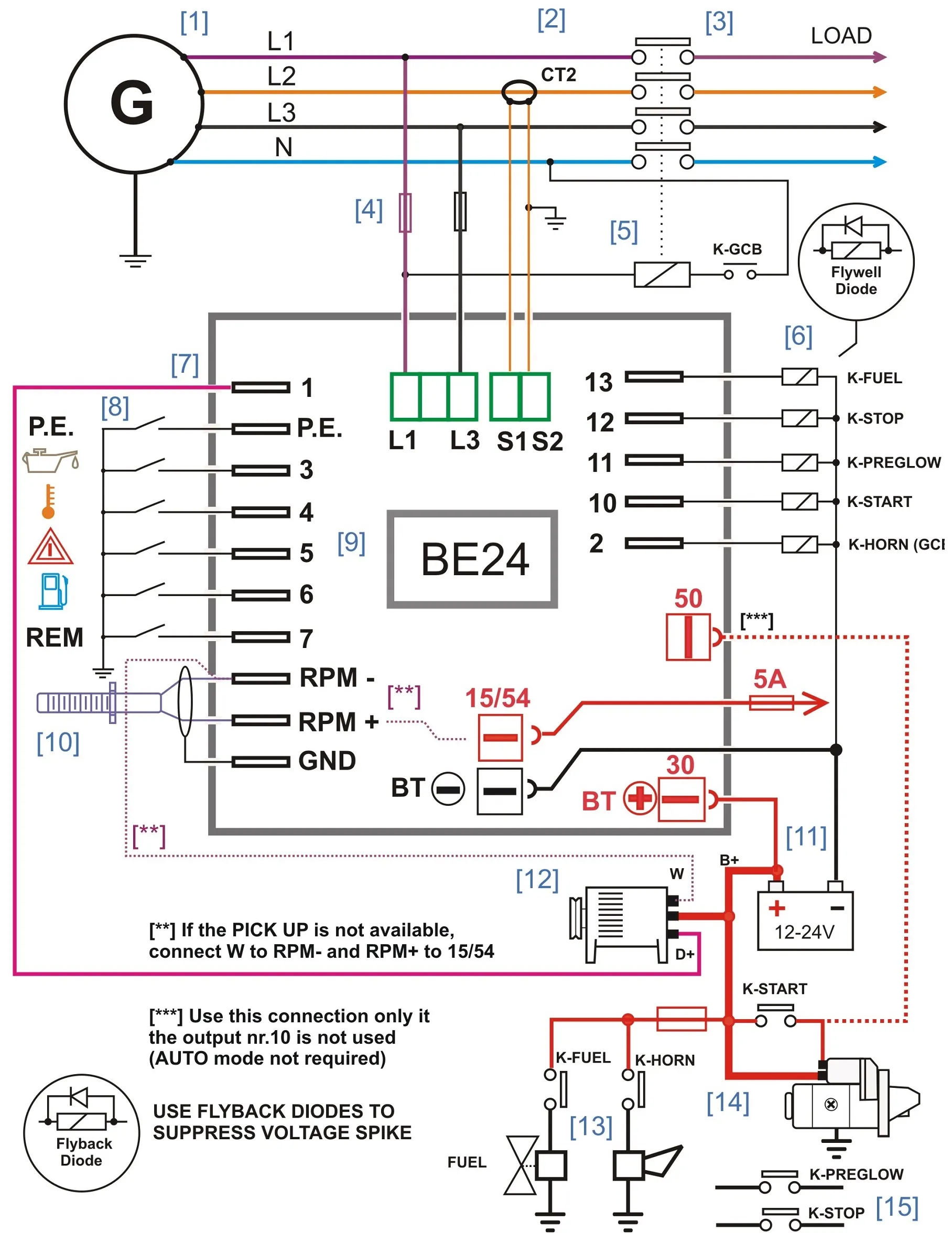
Diagram 3: The Advanced Industrial Configuration (Be124)
If you need remote data communication, you can choose a generator control panel wiring based on the Be124 generator controller. You will benefit from the advantages of CAN bus and MODbus. You can easily connect GSM and TCP-IP modules, maintaining a compact and rational wiring
• Best For: Complex standby installations, rental generators, or panels requiring remote telemetry and sophisticated programmable logic.
• Wiring Focus: Auxiliary configurable inputs/outputs, magnetic pickup (RPM) speed sensing, communication serial links, and comprehensive digital sensor scaling.
How Much Be124 Will It Cost?
Qt. |
Unit Price |
Total (EXW) |
12 |
168 € |
2.016 € |
24 |
157 € |
3.768 € |
48 |
136 € |
6.528 € |
96 |
94 € |
9.024 € |
Click to get Full Size
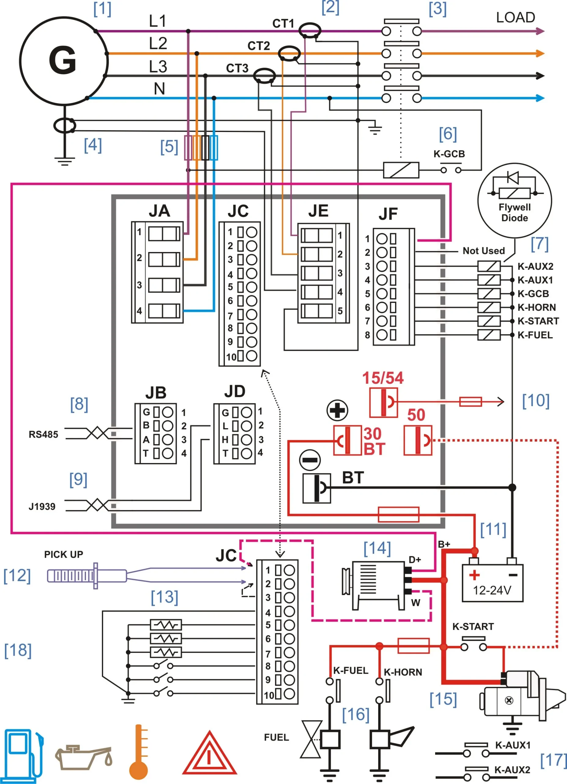
Be124 Advanced Industrial Wiring & Configuration
• Voltage Monitoring: The controller monitors 3-phase mains and generator voltage via the removable terminal block JA. For optimal measurement stability, connecting the neutral wire is strongly recommended.
• Circuit Protection: External fuses are recommended to protect the internal wiring harness.
• Current Sensing & Protection: To achieve comprehensive generator protection, install 4 current transformers (CTs) of a suitable size. The CT ratio is fully configurable up to 1000A / 5A.
• Load Isolation: For maximum load protection, install a primary contactor to immediately isolate the load if electrical parameters exceed safe operational limits.
• Analog & Digital Sensors: You can connect a wide variety of analogue or digital sensors. Ensure that terminal JC4 is properly connected to guarantee optimal sensor measurement accuracy.
• Speed Sensing & Governing: The controller supports speed control and protection via magnetic pick-up or alternator frequency. Alternatively, speed measurement can be sourced via the belt-driven charging alternator terminal W.
• Crank Termination: The unit features flexible, programmable settings to ensure safe and reliable automatic crank termination.
• Configurable Outputs: A total of six short-circuit-proof configurable outputs allow you to easily adapt the wiring diagram to diverse standby generator applications.
• ECU & CANbus Integration: If your engine features an Electronic Control Unit (ECU), connect the CANbus port to drastically simplify the overall wiring layout.
• Remote Communications: Use the removable terminal block JD to connect the RS485 serial cable for remote control and monitoring.
Engineering Note:
Always ensure proper earth bonding of the generator frame and isolate control DC commons from high-voltage AC lines to prevent noise induction on sensitive analogue inputs.
Why Bernini Design Generator Controllers Feature the KG-output
If you are looking for optimal protection for your load and generator, you must always use a contactor. Firstly, it connects your load only when the generator voltage is stable and after a suitable warm-up time. This ensures you supply the load with nominal electrical parameters. Secondly, if the electrical parameters—especially current—are no longer within preset limits, the contactor will immediately isolate your load. Last but not least, normally disconnecting the load allows the generator controller to run its proper cool-down cycle.
Bernini Design Generator Controllers Feature Static Outputs
Bernini Design is focused on providing long-term reliable controllers. Our main objective is to design products that last for decades. Relays are always a bottleneck in generator and automatic mains failure systems.
These components suffer ageing due to electrical stress, vibration, and climate conditions.
We design our controllers with durable, short-circuit-proof static outputs. In other words, you can choose suitable external relays for your applications with the proper current rating. In case of failure, they can be easily replaced, especially if installed over a socket. Any kind of trouble with the relays will not affect the controller itself. The final result is a robust system that is easy to maintain.
We strongly recommend that you insert flyback diodes in parallel with the relay coils to ensure fast switching and reduce electrical interference.
Bernini Design Srl
Zona Industriale
46035 Ostiglia (Italy)
bernini@bernini-design.com
+39 335 70 77 148