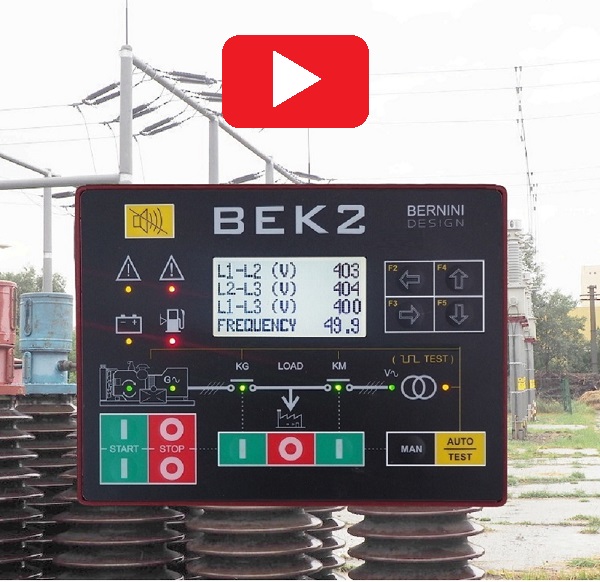
What is an AMF Control Panel?
The AMF control panel features electronic devices that allow you to monitor the functions of the backup power generator.
WHAT IS AN AMF CONTROL PANEL PDF
An AMF control panel is not an AMF panel.
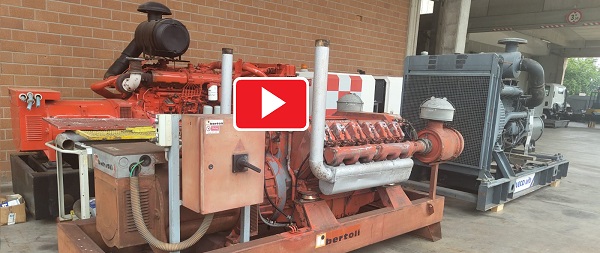
You can purchase an old generator as old as 40 years! Our panel will manage all of it. Follow our tutorial.
 Are you confused about AMF and ATS panels?
We manufacture generator control panels since 1984. You will find on the internet hundreds of useless information about this matter.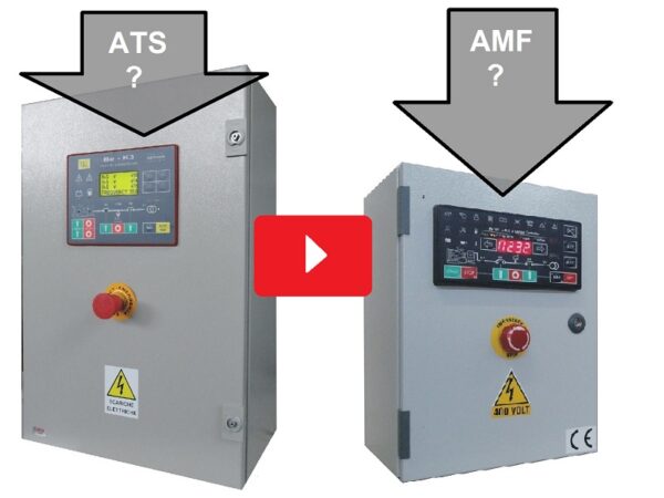
Stay tuned on this page if your business is to make AMF and ATS panels.
The AMF control panel is a processor-based electronic board with miscellaneous components: LED indicators, displays, relays, electronic components, and terminal blocks. it is usually assembled in a rugged IP62 enclosure. This is the basic component of an AMF panel.
If your business is installing standby power generators, visit the page
BEk3 AMF Control Panel Price
You can pay online or ask for a Proforma Invoice and pay via bank transfer
129€
FREE-SHIPPING WORLD-WIDE
20 DAYS DELIVERY TIME
SUPPORT
+39 335 70 77 148
MAYBE YOU ARE INTERESTED IN TWO PIECES. THERE YOU ARE OUR OFFER
PURCHASE 2 PCS
99€/each
FREE-SHIPPING WORLD-WIDE
20 DAYS DELIVERY TIME
You can pay online or ask for a Proforma Invoice and pay via bank transfer
SUPPORT
+39 335 70 77 148
We apply special discounts of 20% 40% for bulk orders
AMF Control Panel Description
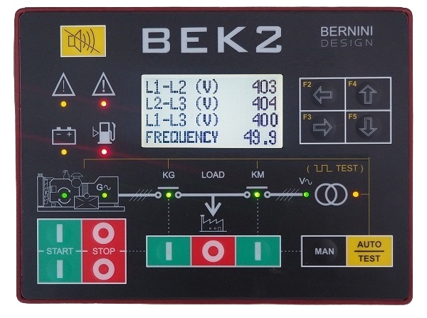
The BeK2 AMF control panel features a 128X64 graphic display, operating in a temperature range between -15°C and +50°C, indicating parameters, alarms, and miscellaneous functions. The AMF control panel measurements include Vac, Aac, Vdc, kVA, kVar, kW, Energy, Pf, Hz, hour count, R.p.m., Oil Pressure, Engine Temperature, Battery Vdc (Engine), and Fuel Level.
The BeK2 control panel complies with NFPA-110 / NFPA-99 specifications. The Be-K2 controller is the best choice when making an AMF panel that interfaces with an old or second-hand generator. The BeK2 features 10 programmable inputs. You can set the input in analogue or digital mode to perform dedicated tasks. The 7-static short-circuit-proof outputs are fully programmable. The rich set of over 150 adjustable settings makes this AMF control panel the most advanced piece of AMF controller available today in the market.
How to get the most from an AMF control panel
Follow our advice. We have made AMF panels since 1984. We have 40 years of experience servicing AMF panels for industrial, telecom and specific applications.
VISIT OUR AMF PANEL MANUFACTURING WEBSITE
STEP 1
Never install an AMF control panel on the generator. It would help if you carried all 400V cables from the mains into the generator. This is extremely dangerous in case of lightning. You will get 100% trouble on your generator.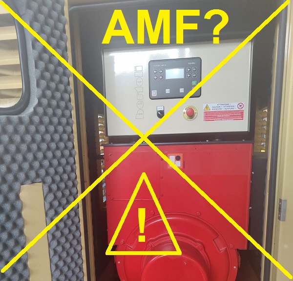
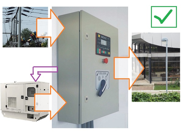
STEP 2
This is the right way to manufacture a long-term reliable AMF panel. The utility power will never affect the DC circuits of the generator. All overvoltage will be shut down inside the panel. It will act as a Faraday cage,
THE BEK2 IS A "ROCK SOLID " AMF CONTROL PANEL WITH AN ENCLOSURE MADE OF STEEL
We do not use plastic materials in our reliable AMF control panels. The enclosure of the BeK2 control panel is made of zinc double-coated steel. Zinc is a heavy element, and when alloyed with other metals, it provides better corrosion resistance, stability, dimensional strength and impact strength.
The rear cover made of metal is the best solution for shock-proof equipment. It is an excellent protection against electromagnetic fields by enclosing the 32-bit processor into a Faraday cage. The BeK2 AMF control panel provides an extraordinary advantage over competitors' plastic-based enclosures.
INGRESS PROTECTION IEC60529 SILICON GASKET UV-PROOF
The BeK2 AMF control panel, thanks to a silicon gasket, is IP65-compliant.

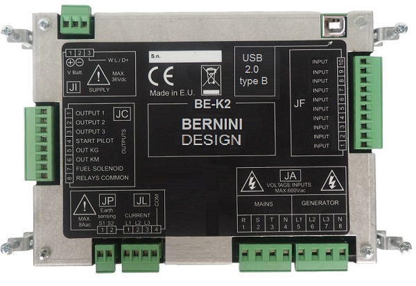
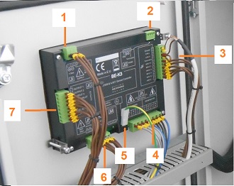
INSIDE A BEK2-BASED PANEL OVERVIEW
[1] Power supply [2] Modbus port [3] Digital / Analog Inputs [4] Generator & Utility power connections [5] Protection Ground [6] Current transformers
THE CHANGEOVER EXPLAINED
There are two basic solutions to transfer the LOAD to GENERATOR or UTILITY POWER: by contactors and by motorized transfer switches. The matter is quite complex. You can find a tutorial on this link
CONTACTORS VERSUS MOTORIZED SWITCHES
In a few words, we can say that it is preferable to use contactors changeover when the total power is up to 100kVA. Over this power, it is better to use motorized switches. In particular cases, a combination of both is required.
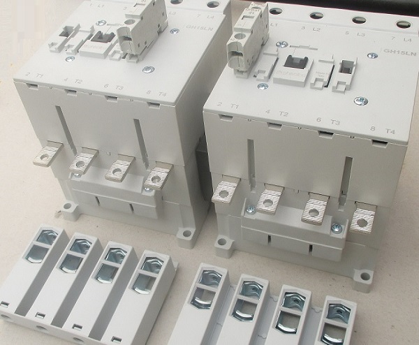
THIS IS A CONTACTOR-BASED CHANGEOVER
The changeover is made by two contactors capable of carrying the nominal current of the panel. This is in the range from 63 amps up to 250 amps. The contactors are activated and held in position by electric coils. On each contactor three are auxiliary contacts. The two contactors are interlocked. In this way, only one contact can be activated.
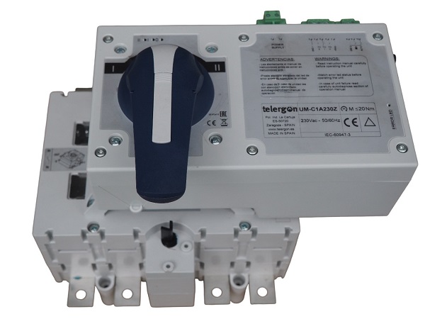
THIS IS A MOTORIZED-SWITCH-BASED CHANGEOVER
The motorized changeover switch is a complex piece of equipment. An electric motor moves the switch to a desired position. Before closing a circuit, the switch is always placed in the OFF position. The motorized transfer switch can manage an enormous amount of current. Once the switch is in position there is no current consumption because there are no coils. On the other hand, you can not pretend flexibility of use. It finally requires a special driving electronic board.
AMF control panel wiring diagram based on contactors changeover
The BeK2 AMF control panel governs the system and transfers the load to the generator or mains smoothly and with short downtime. This AMF control panel wiring diagram shows the basic connections of the BeK2 AMF control panel. It monitors all electrical parameters of the utility power and automatically starts the engine via relays. This happens after a mains failure programmed delay (seconds, minutes or hours).
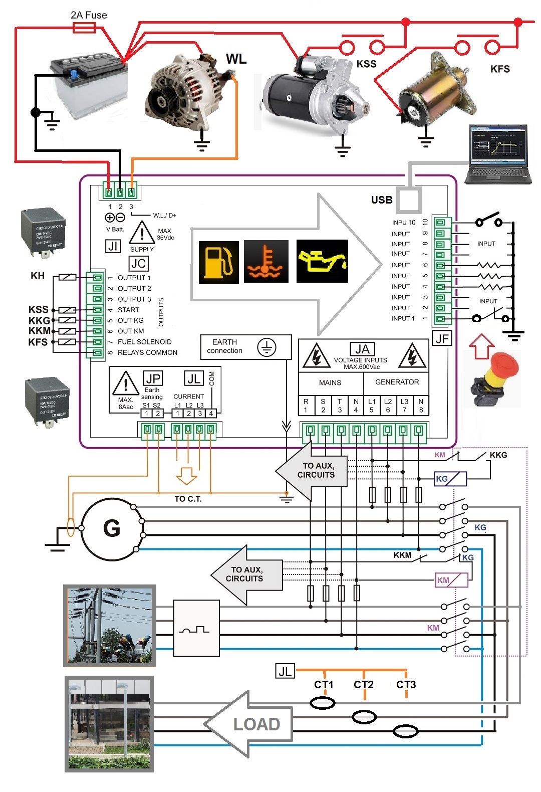
When the engine is cold, the AMF controller waits for a warm-up. The engine will run offload. Once the generator provides the correct frequency and voltage, the controller transfers the load from the mains to the generator. This could be done via a contactor changeover or a motorized transfer switch, Once the mains has been restored, the AMF control panel will connect the load to the mains automatically. After a time delay, the engine is then stopped.
HOW DOES THE AMF CONTROL PANEL WORK?
The BeK2 control panel activates the KG (contactor of the generator) using the KM-AUX and KG-PILOT contacts.. The KM-AUX are the auxiliary contacts fitted on the body of the utility power contactor (KM). When the KM is open, the KM-AUX contacts enable the KG. The AMF control panel finally activates the KG via the KG-PILOT relay. When the AMF control panel switches the generator to the utility power, the user observes a short ‘power outage’. Normally it is about 2 seconds. This is the typical behaviour of the automatic transfer switch: BREAK-BEFORE-MAKE.
AMF CONTROL PANEL UTILITY POWER-LOAD
The KM contactor connects the LOAD to the utility power. The coil of the KM energizes via the KG-AUX and KM-PILOT contacts. The KG-AUX auxiliary contacts have a mechanical connection with KG. The contacts close when the KG opens. The KM-PILOT is the utility power control relay. This relay is OFF when the mains is within the settings. Using the normally closed contacts, we prioritise the utility power in case the AMF controller is damaged or without supply. In case of utility power failure, the AMF controller energizes the KM-PILOT. The KM-PILOT contacts will open the KM. Once the KM is open, the auxiliary contacts KM-AUX will close.
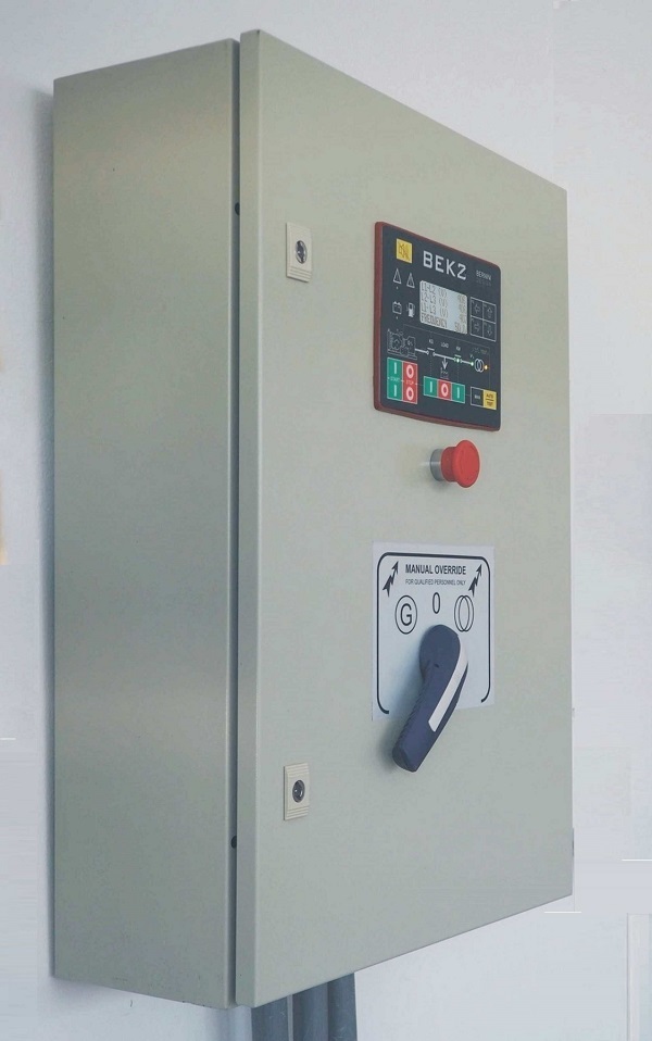
A USER-FRIENDLY AMF CONTROL PANEL
[1] Multi-functions button [2] Shut down indicator [3] Engine control panel [4] Changeover manual control 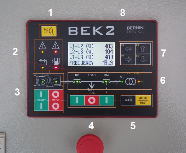
[5] Mode of operation selection [6] AMF panel indicators [7] Navigation buttons [8] LCD Display
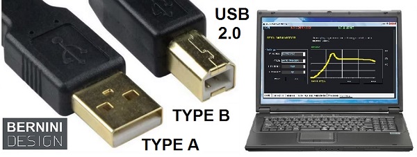
HOW TO SET THE AMF CONTROL PANEL
Despite the possibility to set up the controller by using the navigation buttons and display, the BeK2 control panel offers a USB 2.0 connection. You can plug a B-TYPE male connector on the Be-K3 and an A-TYPE male connector on your computer. The software is provided free of charge.
AMF CONTROL PANEL GENERAL FEATURES
80 OPTIONS FOR EACH ADJUSTABLE OUTPUT
5-PROGRAMMABLE LE RELAY OUTPUTS
35 OPTIONS FOR EACH ADJUSTABLE INPUT
9-PROGRAMMABLE DIGITAL INPUTS
200 EVENTS LOG HISTORY TAGGED BY R.T.C.
600VAC 3-PHASE VAC MONITORING
EARTH FAULT MONITORING
OVER 150 ADJUSTABLE SETTINGS
14-BUTTON INDUSTRIAL CONTROL PANEL
GRAPHIC 128X64 LCD DISPLAY
GENERATOR INSTRUMENTS
ENGINE INSTRUMENTS
DRIVES MOTORIZED CIRCUIT BREAKER
AMF CONTROL PANEL SPECIFICATIONS
Supply voltage:
5.5Vdc to 36Vdc, 50-150mA
Protection:
internal 300mA thermal fuse
Dimensions:
192mm X 144mm X 40mm
Panel Cut-out:
187mm X 139mm, indoor operation
Operating temperature range:
-25 deg C up to +70 deg C
Humidity range:
5% up to 95% non-condensing
Weight:
710 grams
Ingress Protection:
IP62
General design:
ECC 89/336, 89/392, 73/23, 93/68, IEC 68-2-6
Certification:
CE
Static output characteristics:
300mA/100Vdc short circuit proof, negative.
Supply output for relays:
Max 1A at V battery minus 1Vdc (short circuit proof)
Mains and Generator voltage input:
Nominal Voltage input: 70 Vac-600Vac
Overvoltage: 4KVac phase to neutral
Measurement precision:
+/- 2%. Input impedance: 2 Mega Ohm
Current transformer input size:
10/5Aac up to 9900/5Aac
Maximum admissible permanent current:
7Aac
Measurement precision:
+/- 2%. Internal resistance: 0.05 Ohm
Digital inputs Open circuit voltage:
Battery voltage minus 2V - Trigger level: < 2V
Charger alternator monitoring:
Operating voltage up to 36Vdc/3W, accuracy +/- 5%
CONTROL PANEL OUTPUTS
On the removable connector JC you are required to wire auxiliary relays. The BeK2 AMF control panel provides a common supply rail (JC8) suitable for automotive relays providing at the same time over-voltage protection, short circuit protection, and EMI protection. You are required to use 90-200 OHM DC coil relays (12 V or 24 according to your engine battery).
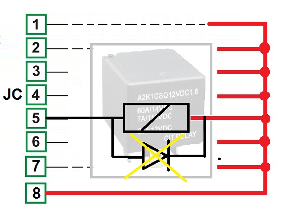
The flywheel diodes are included in the controller.
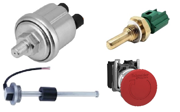
CONTROL PANEL INPUTS
The connector JF is used for the ANALOG and DIGITAL sensor fitted on the engine. You can use various sensors. Default settings allow the use of VDO-CONIINENTAL devices. You can change the setup in a range 0 up to 2000OHM.
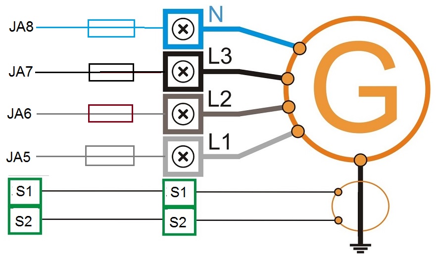
Vac CONNECTIONS
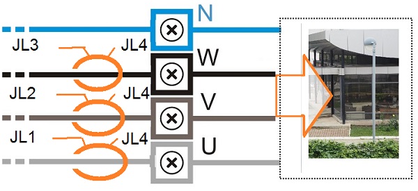
The JA removable plug is used to connect the Mains & Generator voltages. Electrical parameters must be in the range of 80-600V and 20-99HZ. The removable connectors JP and JL are provided for the connection of the CURRENT TRANSFORMERS suitable for the current monitoring of the EARTH FAULT and the current monitoring of the 3-PHASE GENERATOR. Use suitable current transformers for your application.
IT IS MANDATORY TO PROTECT THE CABLES INSIDE THE CABINET! INSTALL 10 AMPS MAX FUSES OR CIRCUIT BREAKERS
The JA removable plug is used to connect the Mains voltages. Electrical parameters must be in the range of 80-600V and 20-99HZ.
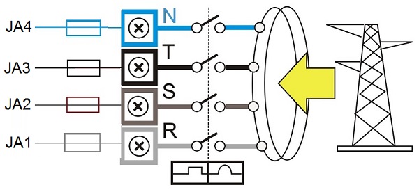
Connect the current transformer on the LOAD side. In this way you will get current measurements all the time, When you set an overload warning or shutdown, only the measurement from the generator will cause the alarm.
AUTO MODE OF OPERATION
Push the [AUTO] push button until the yellow LED illuminates. The engine starts when the BeK2 detects a Mains failure (see section 9.01 for settings). The Mains circuit disconnects the LOAD after the [MAINS BREAKER] timing. After the [WARM UP] time if the voltage and frequency are within the settings, the circuit breaker of the Generator will close. If the Mains restores, the KG will open. The KM will close following a programmed [KM CHANGEOVER] timing. The engine will stop after a [ COOL DOWN ] time. If the engine shuts down, because of an alarm, the KM closes independently of the Mains status if the [ NFPA-110 ] is on, otherwise, the KM will close only if the parameters of the Mains are within the programmed settings. In AUTO mode, the BeK2 will periodically test the engine if the periodic test is correctly programmed. During the test, the yellow LED of the AUTO mode will continue to blink. The BeK2 can start and stop the engine if the remote control is activated.
TEST MODE
Push and hold the [AUTO] push button until the yellow LED starts to blink. The BeK2 will start the engine and transfer the load to the Generator only in case of Mains failure if not otherwise programmed by the parameter [KG TEST CONTROL]. To exit the TEST mode, push the [AUTO] push button shortly or select another mode of operation.
BERNINI DESIGN SRL
ITALY
Industrial Park
46035 OSTIGLIA
SUPPORT
+39 335 70 77 148