Be172: The Rugged, Universal Key Start Module for Diesel Engines.
Plug-and-play retrofit for any diesel engine.
-40°C to +85°C Operating Temperature Range.
Military-grade display, vibration-proof reliability.
Fully coated electronics parts.
Full-Service Private Label Manufacturing.
Compatible With Be72 Key Start Module.
Use the Be172 to easily upgrade outdated or broken key switches on your diesel machine.
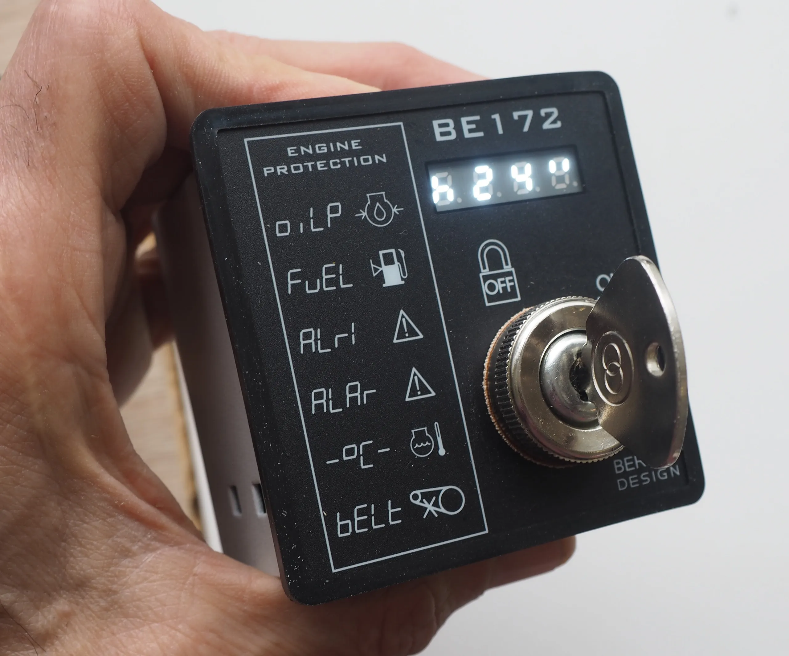
The Be172 key start module includes the basic safeguards to protect a diesel engine. It features a 4-digit military-grade 7-segment display, 3 static outputs, 7 digital inputs, and a 30Adc-rated key switch. First of all, it monitors an oil pressure switch, a temperature switch, a fuel level switch, a charger alternator voltage and auxiliary alarms, offering also 4 adjustable settings for pre-glow, fuel solenoid, fuel and auxiliary alarm. The Be172 is an upgrade of the most popular Be72 engine protection module. The display indicates ENGINE HOUR COUNT, BATTERY VOLTAGE, ALARMS, and INTERNAL SETTINGS

The display indicates battery voltage & h-counter. You can adjust, on-site, PRE-GLOW timing, several timing options for STOP SOLENOID, Fuel Alarm Shut-Down options, Auxiliary Alarm Options, and other miscellaneous functions.
DOWNLOAD> BE172 INSTALLATION MANUAL
A rustproof, rugged steel supports the tropicalized electronic boards. A gasket made of a special polymer protects against the elements. Make a standard cut-out through-hole suitable for DIN 72 panel instruments. Two fixing clips made of steel offer a high degree of mechanical safety in case of shock and vibrations.
Purchasing the Be172, designed and built in Italy
Request a formal quote to bernini@bernini-design.com
You can purchase online or ask for a proforma invoice via WhatsApp or email. In either case, specify the full address and phone number. The average delivery time is 10 days with free shipping. This includes processing and transit time.
Download the Be172 installation manual (PDF)
For an express delivery, we can use FedEx or DHL with an extra fee depending on your address.
WhatsApp +40 721 241 361
Gsm +39 335 70 77 148
PURCHASE ONE SAMPLE
129€
FREE SHIPPING WORLDWIDE
PURCHASE TWO PIECES
2 x10⁹€/each (218€)
FREE SHIPPING WORLDWIDE
PURCHASE FOUR PIECES
4 x 69.00€/each (276€)
FREE SHIPPING WORLDWIDE
Why and When to install the Be172?
The WHY: it is user-friendly, rugged, cost-effective, and designed to last for decades. It operates reliably in a range of environments, from minus 30 up to 70 degrees Celsius. The solid-state display can operate between -40/+85 degrees Celsius, rated as a solid-state, white light LED display. It is the best choice for high-vibration machinery: the Be172 is both rugged and vibration-proof.
The WHEN: you are going to manufacture a new piece of machinery, retrofit any kind of diesel machine or you want to upgrade the Be72 Key Start module
What is Be172 suitable for?

We designed the Be172 to replace the most common, fragile modules in the field. It’s built to survive in environments where others fail, using a solid-state LED display and a rugged steel frame. If you have any questions about fitting this to your specific engine, message us directly on WhatsApp

+40 721 241 361
AGRICULTURE ENGINES
MARINE ENGINES
HEAVY MACHINERY
COMPRESSORS AND GENERATORS
A User-Friendly Key Start Module
A) - When the KEY is in position ‘OFF’, a white dot blinks on the right side of the display. This indicates the standby mode. All the time you turn the KEY to ‘OFF’, the display indicates the [HOUR COUNT] for about 10 seconds (for example [h 278]). Then, the display turns off. The ‘OFF’ mode clears all alarms.
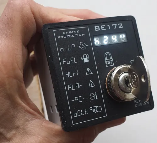
B) - Turn the KEY to ‘ON’. The display indicates the battery voltage for 3 seconds (for example [b 12.6]).
C) - When the display indicates the prompt [StA-], turn the KEY to ignition. When the Be172 detects oil pressure or voltage on the charger alternator, a rotating animation will be displayed.
D) - Turn the KEY to ‘OFF to stop the engine. The display, before shutting down, will indicate the [HOUR COUNT] for a few sevconds. The Be172 absorbs as low as 8mA of current.
For detailed user instructions, download the user manual
Safety First: The Alarms List
In the case of pre-alarm, a particular messages blinks on display. Once the engine stops, the first cause of shutdown freezes the message on the display until you turn the key off.
[bELt] Engine Belt break or Charger failure shutdown. The Be172 triggers this alarm and shuts down the engine if the input (D+/W.L) is continuously missing for at least 20 seconds. This alarm is ignored during the first 8 seconds after starting the engine.
[°C] Engine High-Temperature alarm. The Be172 triggers this alarm and shuts down the engine if the switch input (°C) is closed for at least one second. This alarm is ignored during the first 8 seconds after starting the engine.
[ALAr] Emergency alarm. The Be172 triggers this alarm and shuts down the engine if the switch input (ALR) is closed for at least one second.
[FuEL] Fuel level alarm. The Be172 triggers this alarm if the switch input (FUEL) is closed for at least one second. Based on the settings of the parameter [P3], the BE172 triggers a warning (it features auto-reset) or shuts down the engine after a programmable time.
[ALr1] Alarm 1. The Be172 triggers this alarm if the switch input (SPARE) is closed for at least one second. Based on the settings of the parameter (P4), the Be172 triggers a warning (it features auto-reset) or shuts down the engine after a programmable time.
[oiLP] Low oil pressure. The Be172 triggers this alarm and shuts down the engine if the oil pressure switch connected to the (OIL) input is closed for at least one second. This alarm is ignored during the first 8 seconds after starting the engine.
[FAIL] Fail to start alarm. The Be172 triggers this alarm and shuts down the (FUEL) output if it does not detect, within 20 seconds, a valid source of engine running from terminal (D+/WL) or a valid transition of the (OIL) input (closed-to-open).
[bXX.X] This message blinks to indicate a low/high battery voltage (11.8/15,6V & 23.6/31.0V)
With simultaneous alarms, the display indicates messages in a suitable sequence.
The Adjustable Settings Menu
The controller is supplied with default settings: 5" pre-glow and 5' alarm fuel shutdown. The Be172 offers the following adjustable parameter settings:
[P1] Pre-glow settings
The available options are: 6”- 15”- 30”- 45”- 1’
[P2] Alarm/Stop solenoid
The available options are: 5”,- 15”,- 30”,- 1’ -2’
[P3] Fuel alarm modes
The available options are: 5’- 10’- 20’-30’- 60’
[P4] Alarm 1 modes
The available options are: 5”, - 15”,- 30”,- 45”,- 1’,- 5’
Follow the user-friendly programming instructions described in our support page:
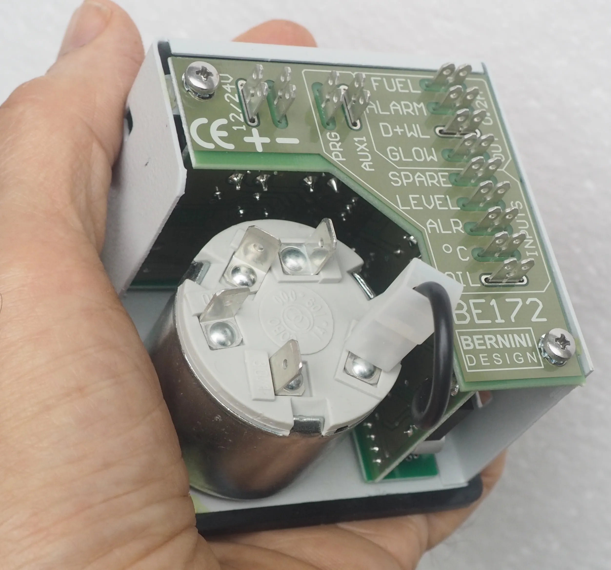
The Be172 Rear View
The connections are supported via 0.8 mm x 6.3 mm, automotive-grade, blade terminals. You are required to connect the inputs to switches [5]. The other side of the switches must be connected to the battery minus. The output 'FUEL' drives a relay suitable for an 'ENERGIZED to RUN' solenoid. This output automatically shuts down when you stop the engine or an alarm occurs. If you need an 'ENERGIZED to STOP' output, program a timing for the parameter [P2]. This transforms the output 'ALR' into a programmable timer suitable for a STOP SOLENOID.
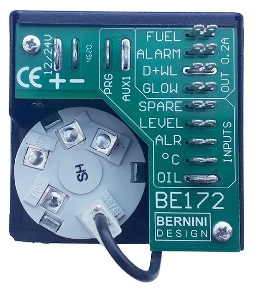
The BE172 features short-circuit-proof outputs capable of supplying 200mA. You can use a 12 or 24-V battery. The connection of the D+ is not mandatory but recommended. Suppress the electric noise of the relays by installing flywheel diodes. The KEY-SWITCH directly drives the starter motor via the terminal [50].
Explore how the Be172 wiring diagram can perfectly fit into your application.
BERNINI DESIGN SRL
INDUSTRIAL PARK
46035 Ostiglia
ITALY
bernini@bernini-design.com
+39 335 70 77 148