What is Automatic Mains Failure?
The automatic mains failure unit takes action to control a standby generator. This maintains your load in supply. The Automatic Mains Failure controller is designed for BTS (Base Transceiver Stations). In other words, it stands for a system capable of monitoring the status of the mains.
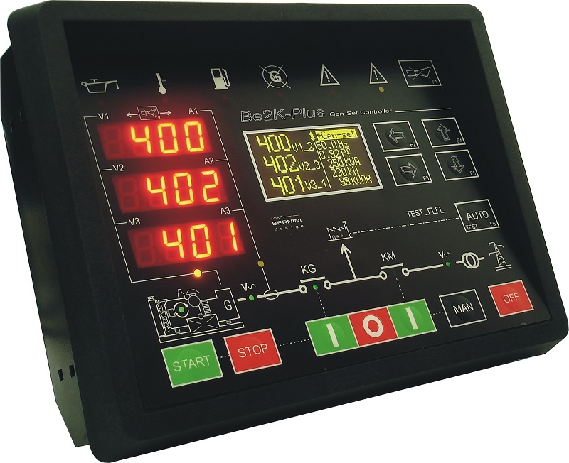
The "Mains" is a British term indicating public utility power. In other words, the "Mains" is the national power grid. In between the Mains and your load, there is the energy counter. In America, the"Mains" is meant to be the Utility Power grid.An AUTOMATIC MAINS FAILURE can be also described as an electronic or electric system that detects a deviation of the electrical parameters.
IN THIS PAGE
What does an automatic mains failure do in the context of BTS sites?
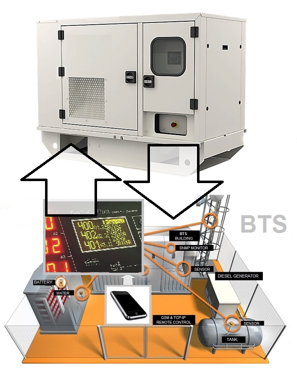 The Be2K Plus automatic mains failure controller is the best option for a Diesel Generator placed in a Base Transceiver Station. It is about a shelter or a building with fundamental equipment that allows wireless communication between the user equipment and a telecom network. Generator monitoring refers to the monitoring of a generator for power, security, and environmental issues that might affect the service of the emergency power system. Bernini Design provides generator monitoring equipment located on the site. The automatic mains failure controller reduces the costs of maintenance. When an outage does occur, service personnel can be dispatched with valuable information regarding what problems they may encounter on-site. The Be2K Plus controller plays an important role in preventing and reducing telecom network outages caused by generator troubles: you can set pre-alarms and modify the setting of the engine or generator to avoid severe damage to the system. It monitors the parameters of the site's utility power, rectifiers & batteries, air conditioner, and other hybrid power types of energy sources.
AUTOMATIC MAINS FAILURE CONTROLLER
The automatic mains failure controller is a combined 3-phase mains monitoring & generator control system. The parameters, the alarms, and operating functions are indicated using a high-performance 128X64 graphic display capable of operating between -30°C and +70°C. The front panel features super-bright solid-state indicators capable of sustaining severe climatic conditions.
Automatic Mains Failure Controller Installation Manual
The automatic mains failure controller interfaces with resistive sensors, 4-20 mA /0-10 Transmitters, and a magnetic Pick-up (or 'W'). Measurements include Vac, Aac, Vdc, kVA, kVar, kW, Energy, Pf, Hz, hour count, R.p.m., Oil Pressure, Engine Temperature, 3 Auxiliary Temperatures, Telecom Battery Vdc, Battery Vdc (Engine), and Fuel Level. This controller is SAE-J1939 compatible and provides RS485 and RS232 interfaces.
AMF CONTROLLER MODBUS PROTOCOL
AUTOMATIC MAINS FAILURE UNIT KEY FEATURES
MULTIPROCESSOR ARCHITECTURE
12-digit Led-Display and 128x64 Graphic (-30°/+70°) OLED Display
Indicates kVA, kVAr, kW, PF, Aac, Vac, Hz, kWh-meter & h-meter
Designed for 750Vac 3-Phase continuous connection
Engine and Generator Instruments
It monitors the ambient temperature and air conditioner
60 INPUT-OUTPUT connections
32 Options for each programmable input & 79 Options for each Output
Earth fault monitoring and Reverse Power
RS485, CAN-BUS J1939, RS232 and TCP-IP
200 Events Log history tagged by a Real-Time Clock
VDC sources monitoring for Telecom & Renewable Energy Applications
Multi-Source Auto Start Features
High-quality manufacturing, 72-hour dynamic burn-in, 3-Year warranty
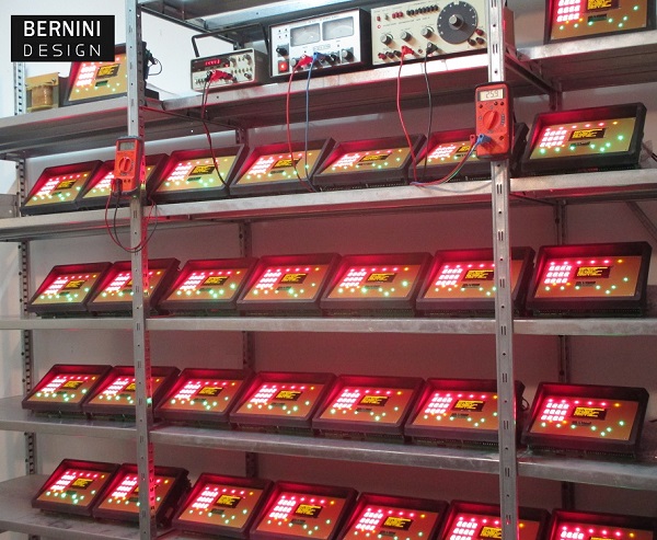
Before delivering the automatic mains failure units, Bernini Design places the products on a testing rack. The automatic mains failure controllers run a 72-hour burn-in test. Additionally, 4 cycles of thermal shock from -30°C up to 85°C are carried out.
Automatic Mains Failure Circuit Diagram
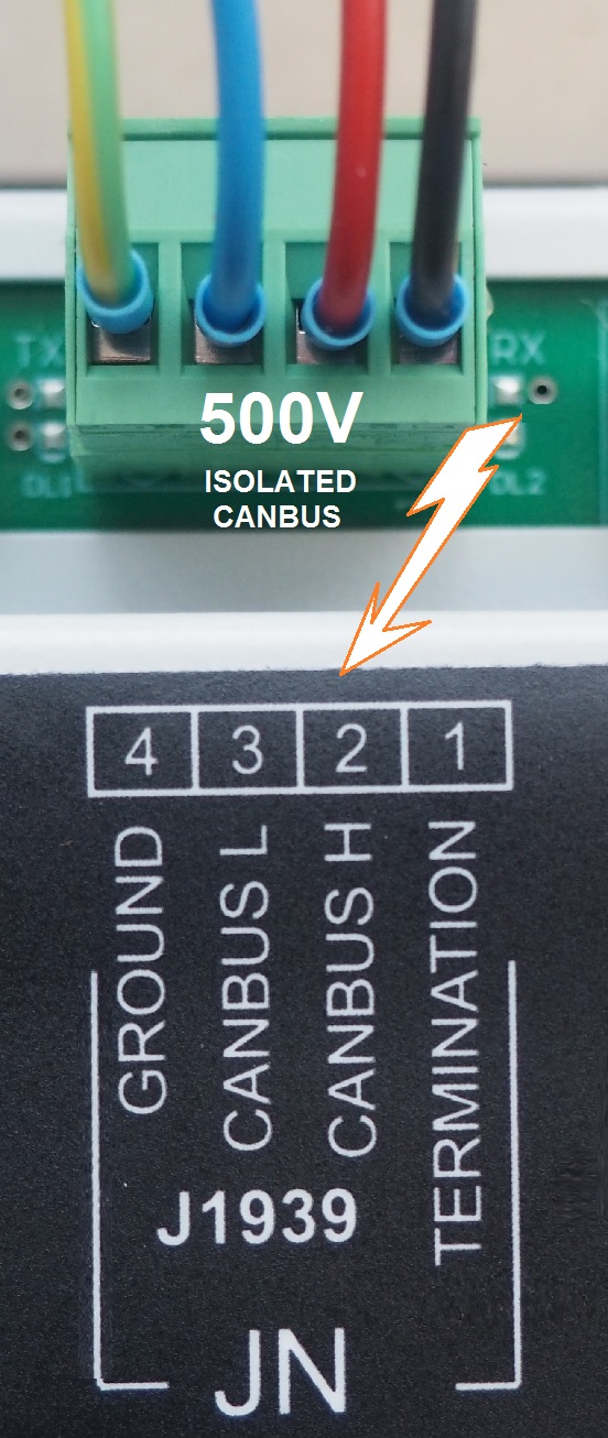
The automatic mains failure control unit interfaces with all kinds of engines, with or without ECU. In case you have a CANBUS J1939 compatible engine, the Be2K-Plus offer a suitable menu for the choice of the engine manufacturer. The CAN BUS port is fully isolated. To interface a standard engine, without ECU, you must install automotive relays. A removable 10-pole connector JC supports all necessary outputs to control the engine. This includes the belt alternator excitation circuit. You can find additional auxiliary outputs available on the connector JB. All outputs of the automatic mains failure controller are via static NPN transistors. The outputs are short-circuit proof. The recommended output current is about 200mA.
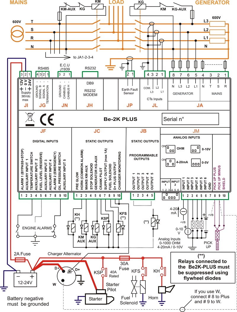
On the connectors JF and JM you can connect digital and analogue inputs suitable for your applications, The AMF controller offers a rich set of settings. You can configure the inputs to adapt the controller to your application.
AMF CONTROL PANEL CIRCUIT DIAGRAM PDF
On the connector JM you can connect a pickup, sensors, and analogue transmitters. The connectors JA, JP and JL are reserved for the generator monitoring, We recommend that you wire suitable fuses to protect the wires in case of a short circuit. You can set parameters to start/stop the engine according to a combination of mains failure, battery auto start, and air conditioner. The concept is to run the generator only when necessary, with the final goal of fuel economy. The automatic mains failure unit features separated and isolated RS485, RS232, and CANbus. You can connect the Be2k-Plus via TCP-IP and/or GSM.
THE BE2K-Plus CONNECTIONS and REAR VIEW
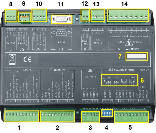
[1] DIGITAL INPUTS [2] DIGITAL OUTPUTS [3] DIGITAL OUTPUTS [4] ANALOG INPUT SELECTION [5] ANALOG INPUTS [6] ANALOG INPUT TRUE TABLE [7] SERIAL NUMBER [8] POWER SUPPLY PLUG [9] RS485 PORT [10] CANBUS PORT [11] RS232 PORT [12] EARTH FAULT SENSOR [13] CTs CONNECTION [14] MAINS & GENERATOR CONNECTIONS
Automatic Mains Failure Unit Front Panel Overview
The interface of an automatic mains failure controller is user-friendly. The commands are intuitive. The high-intensity LED are visible in direct sunlight. The front panel features IP68 buttons capable of 500.000 operations in the extreme temperature range. The tactile feedback is extraordinary even if you wear protective gloves.
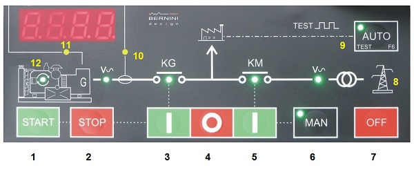
[1] MANUAL START [2] MANUAL STOP [3] GCB [4] OPEN A CB [5] MCB [6] MANUAL MODE [7] OFF MODE [8] MAINS STATUS [9] AUTO MODE [10] CURRENT MODE [11] VOLTAGE MODE [12] ENGINE RUNNING
ENGINE ALARM INDICATION ASTONISHING LAMP TEST
[1] LOW OIL PRESSURE [2] ENGINE TEMPERATURE [3] FUEL ALERT [4] GENERATOR FAILURE [5] RED LAMP ALARM [6] AMBER LAMP ALARM
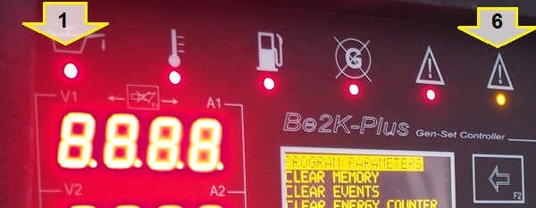
Firstly the most critical alarms are directly indicated by high luminosity LED. Secondly, the Be2K-Plus displays and records over 100 alarms with date and time information. The red alarm indicators feature up to 8000 mcd luminosity: very well visible in sun-light conditions
AUTOMATIC MAINS FAILURE CONTROLLER FEATURES A MASTER MENU
The MASTER MENU is the general index of the automatic mains failure controller. It appears in the OFF mode of operation only. It provides full access to all settings necessary to set up your standby generator. The MASTER MENU features 2 pages with a total of 14 SUB-MENUS. You will have access to 100% of adjustable parameters and settings. From the list on the first page, you find the most common menu suitable for the end-user.
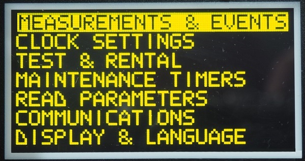
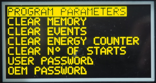
The second page offers access to the programmable settings, operation on the memory and PASSWORDS setup. The second page is suited for installation personnel.
MANDATORY CONFIGURABLE SETTINGS
These two pages contain mandatory settings required by a high-performance automatic mains failure system. These pages are included in the [PROGRAM PARAMETER] main menu.
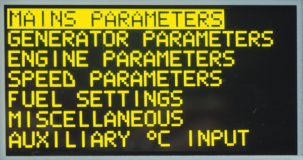
By clicking the [F3] arrow, you can access all available settings
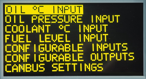
Some basic parameters are already set as default, and, some others are not activated by default. You can adjust your settings on-site by using the buttons on the front panel.
OEM PARAMETERS VERSUS USER PARAMETERS
OEM parameters are "KEY IMPORTANT" parameters that are strictly related to the kind of engine and generator connected to the automatic mains failure system. The USER parameters are dependent on the application. In this case, the user can directly set up the automatic mains failure according to their own need. An example of it is the following menu in which the user establishes the proper moment to start the generator for testing purposes automatically.
THE SCHEDULER
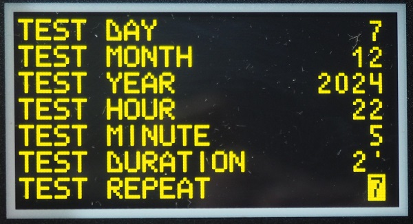
In the above picture, you can see an example of a test scheduler. In this example, the engine will automatically start every 7 days at 22:5 PM for 2 minutes. The first test will trigger the engine on December 7 2024.
AUTOMATIC MAINS FAILURE MEASUREMENT & EVENTS PAGES
In this example, the display indicates that you are going to open the MEASUREMENT & EVENTS SUB-MENU.
Once you push the "RIGHT" arrow, the list of measurements will appear on the display.
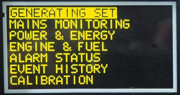
You can scroll down the list and choose to display the parameters you are looking for.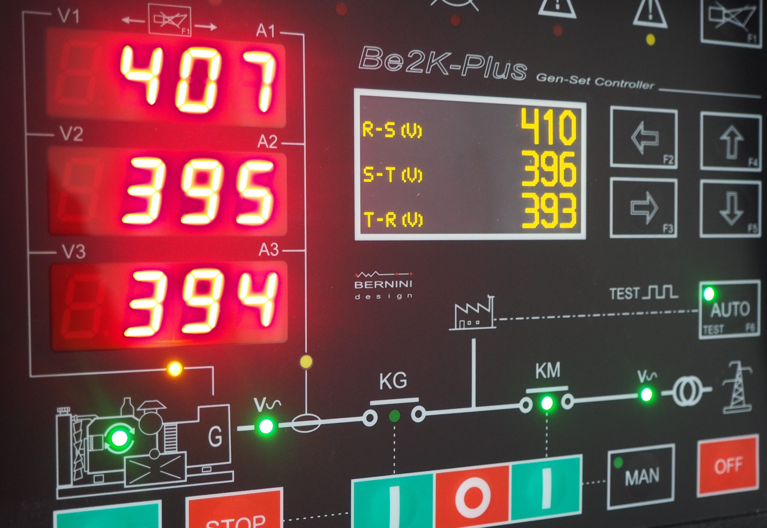 You can observe the reading of the generator voltage on the LED display and the reading of the MAINS on the graphic display. The engine is running in MANUAL MODE of operation. The green LED indicators are regularly on. The MAINS circuit breaker is closed on the MAINS position.
AUTOMATIC MAINS FAILURE CONTROLLER MODES OF OPERATION
ENGINE MANUAL MODE Push the [MAN] pushbutton to select the MANUAL mode. Push the [START] pushbutton until the engine starts; the display will automatically open the ‘ENGINE STATUS PAGE’ with information about the start sequence.
When the engine is running, the ENGINE green LED symbol turns on. To stop the engine, push the [STOP] pushbutton until the [STOPPING] message appears on the display.
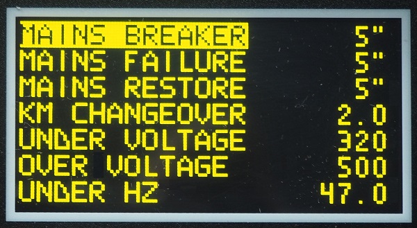
LOAD MANUAL TRANSFER Push the [ KG ] pushbutton to close the generator circuit breaker. To transfer the Load to the Mains wait for the Green Light ‘Mains available’ and push the [ KM] pushbutton: the KG will open and KM will close after a 2-second delay. In manual mode, the automatic mains failure controller ignore the programmable changeover setting.
AUTOMATIC MODE Push the [AUTO] pushbutton until the green LED illuminates. The engine starts when the Be2K-Plus detects a Mains failure. The contactor of the Mains opens after the ‘MAINS BREAKER’ timing. After the ‘WARM UP’ time, if the voltage and frequency are within the settings, the generator contactor will close. If the Mains restores, the KG will open. The KM will close following a programmed ‘KM CHANGEOVER’ timing. The engine will stop after a ‘COOL DOWN’ time. If the engine shuts down, the KM closes independently of the Mains status if the NFPA-110 is on, otherwise, the KM will close only if the parameters of the Mains are within the programmed settings. In AUTO mode, the Be2K-Plus will periodically test the engine if the periodic test is correctly programmed. During the test, the green LED of the AUTO mode will continue to blink. In AUTO mode, the Be2K-Plus can start and stop the engine if a remote control is activated. You can stop the engine at any time by selecting the MAN mode.
TEST MODE Push and hold the [AUTO] pushbutton until the green LED starts to blink. The Be2K-Plus will start the engine and transfer the load to the Generator only in case of Mains failure (if not otherwise programmed by the parameter ‘KG TEST CONTROL’). To exit the TEST mode, push the [AUTO] pushbutton shortly or select another mode of operation.
AUTOMATIC MAINS FAILURE PROGRAMMABLE PARAMETERS
The Be2K-Plus automatic mains failure controller features hundreds of adjustable settings. The following screenshots show the list. You can choose an item from the menu: [MAINS PARAMETERS], for example. The automatic mains failure control will open the complete list of the available parameters for the [MAINS PARAMETERS] menu.
EXAMPLES OF MENU CONTENT
Examples of the two most common and popular menus follow. You will observe the content of the [GENERATOR PARAMETERS] and [MAINS PARAMETERS] menus.
GENERATOR and LOAD PROTECTION
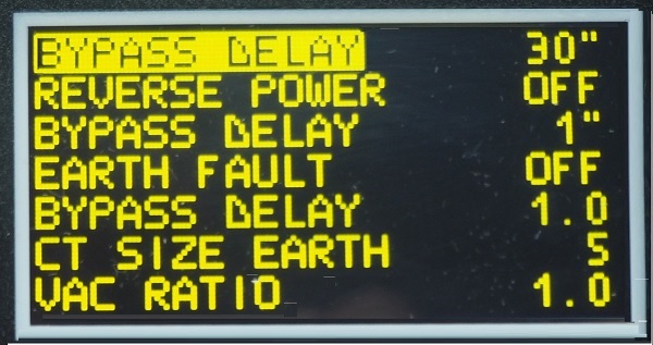
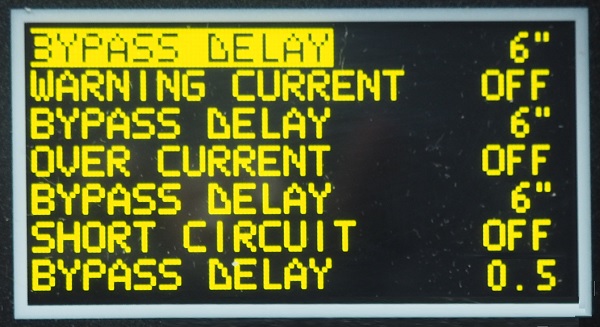
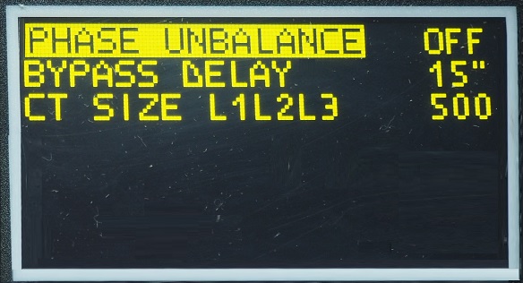
The Be2K-Plus features a complete set of adjustable parameters committed to the protection of your LOAD and GENERATOR. The following screenshots show the list included in the [GENERATOR PARAMETERS] menu.
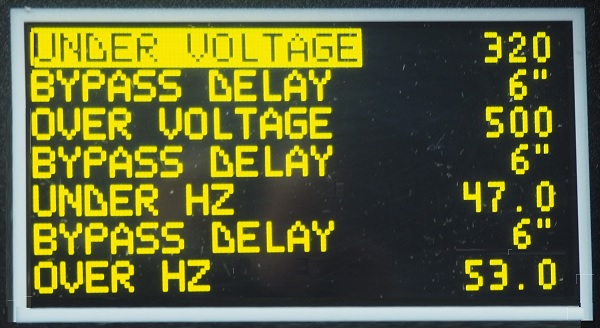
Particularly important in industrial applications are the settings of REVERS POWER and EARTH FAULT. For granular protection, you can use a precise current transformer down to 5:5 amps.
The OVERLOAD settings prevent severe damage to the entire standby system. You can set warning current limits and delays.
 With these settings, you can prevent load damage by limiting the error voltage between phases. You can set here the size of the current transformers.
MAINS FAILURE SETTINGS
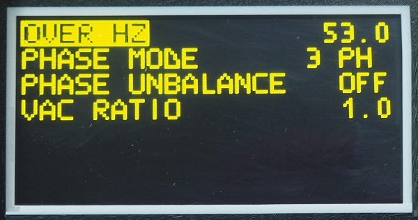
The following screenshots show the list included in the [MAINS PARAMETERS] menu. When it comes to Automatic Mains Failure, the settings of the following parameters are mandatory. The KM CHANGEOVER is particularly critical in industrial applications when the generator must supply large electric motors.
MEMORY and PASSWORDS
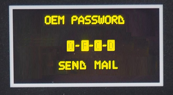
You can set up separate passwords for OEM (installation) and USER (i.e. the final customer). In case you lose the password, the automatic mains failure controller offers a way to recover it. When you generate a password, the Be2K-Plus creates a recovery code.
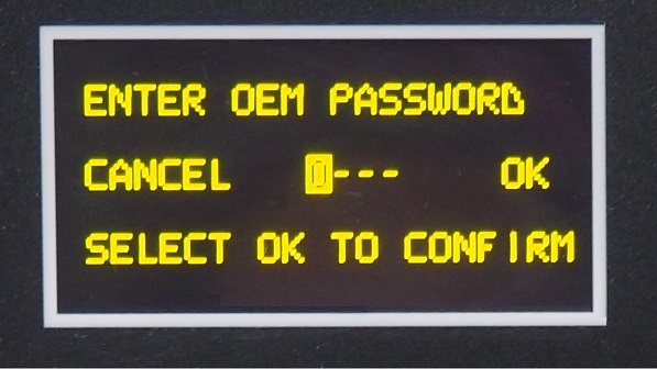
You are required to send the recovery code to us. After verification that you are the owner of the automatic mains failure system, we will send the UNLOCK-PASSWORD via email.
HOW TO MAKE PANELS
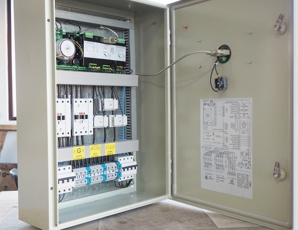
You understood "automatic mains failure" what is about. The key component is the Automatic Mains Failure controller. Building a complete automatic mains failure panel is not an easy task. There are international standards to be observed when you are going to place a product of this kind on the market. If you are not an ELECTRIC PANEL MAKER, we vividly recommend that you contact a specialised manufacturer. You can have some guidance on this website, together with an overview of the available models and prices.
MONITORING FEATURES
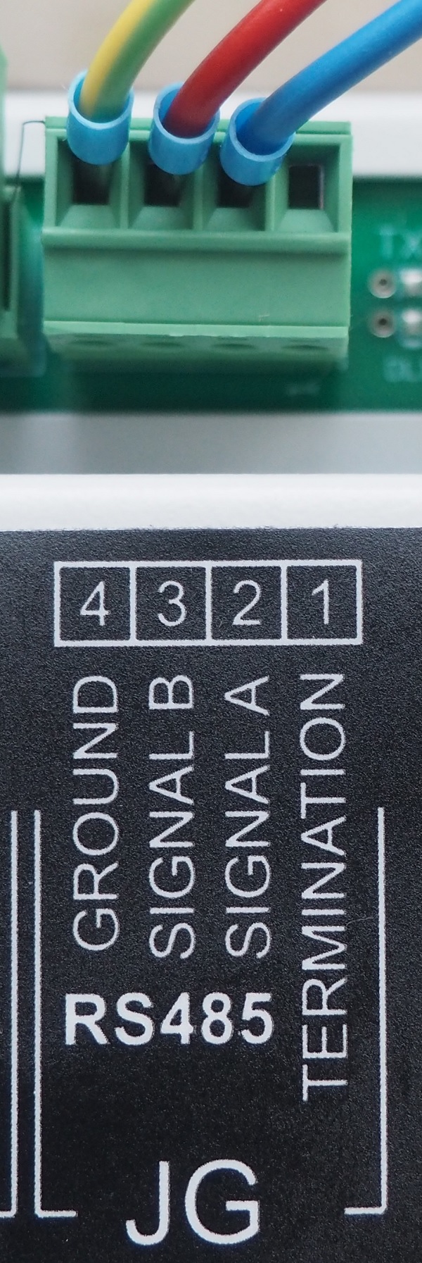
The Be2K-Plus controller features a universal RS485 serial interface capable of driving 1000m of twisted cable with 127 nodes. This port supports a standard MODBUS-RTU protocol. By using the protocol, you can integrate the full functionality of the controller into your factory automation system. We can support you in implementing a TCP/IP connection as well.
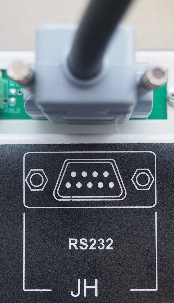
This automatic mains failure controller features a standard RS232 port that supports AT commands. This can be connected to a standard GSM MODEM. In this way, you can get an SMS connection or a full DATA transfer connection.
The automatic mains failure unit supports CANBUS J939. You can connect any compatible engine. This will allow you full control and engine monitoring.
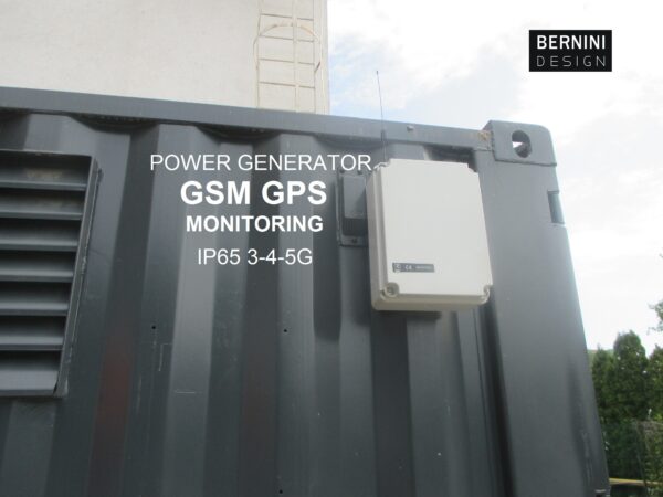
Explore how to control and monitor a diesel generator via TCP/IP, the INTERNET, MODBUS and GSM. Get the most from it.
DIESEL GENERATOR REMOTE CONTROL MONITORING
