BATTERY MONITORING RELAY
KEY FEATURES
USB CONFIGURABLE UP TO 500V
HIGH PRECISION
RAIL MOUNT
SOLAR BATTERY MONITORING
ENGINE BATTERY MONITORING
BE248 GSMBASED VERSION

The Be48 battery monitoring relay is the ideal choice when it is for critical applications. You can easily configure it by using a computer via USB. The measurement precision of the Be48 battery monitoring relay can be calibrated down to 0%.

The Be48 DC voltage monitoring relay can be used to monitor the voltage of your SOLAR BATTERY PACK or to monitor the voltage of the engine battery (usually in the range of 12V to 24V). In this last case, the Be48 will start the engine to maintain the battery in good condition. A set of programmable parameters allows you to set Voltage Thresholds, delay timings, and time-out timing. You can easily interface the Be48 with the most popular auto-start modules.
BATTERY MONITORING RELAY CIRCUIT DIAGRAM
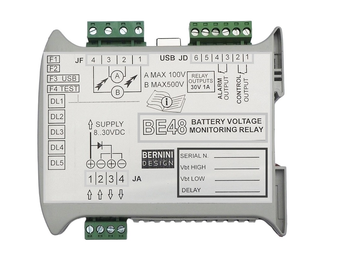
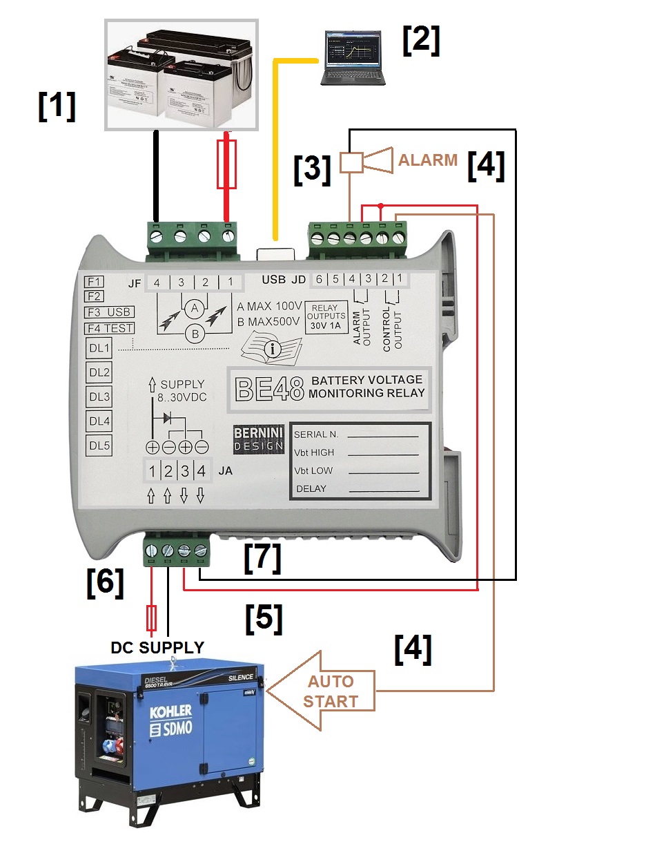
You can supply the BE48 by using a DC source between 8 to 30 Vdc connected to terminals JA1-2 via a protection fuse [6]. The JA3-4 terminals can deliver an electronically limited 300mA current [7]. The inputs JA1-2 are protected from reverse polarity for an unlimited time. To monitor a voltage up 100Vdc connect the terminals JF2-3. For higher voltage, up to 400 Vdc connect the terminals JF1-4. The polarity of the connection does not matter but we highly recommend protecting the wires with a suitable fusE. The following diagram shows general-purpose battery monitoring. If you connect to JF2-3 the battery of the engine, you will get a low battery monitoring of your engine.
THE BATTERY MONITORING RELAY OUTPUTS
You can connect the terminals JD3-4 to drive an alarm indicator and use terminal JD1-2 to activate a power generator [5] via an auto-start module [4]. JD1-2 and JD3-4 are internally connected to 30V 1A relays. Even though the relays are rated 230V-8amp, we recommend that you limit the current to 300 mA (there are internal 500 mA thermal protection circuits). If you drive inductive loads, the use of flywheel diodes is mandatory. In the following diagram, the JD2-3 terminals are connected to Battery Plus. In this way, when Be48 activates the output relays by delivering a positive voltage.
BE48 BATTERY MONITORING RELAY INSTALLATION MANUAL
SUPPORT
+39 335 70 77 148
BE48 BATTERY
MONITORING RELAY
FREE SHIPPING LIFE TIME WARRANTY
DELIVERY TIME 20 DAYS
149€
BE248 GSM-BASED
BATTERY MONITORING RELAY
FREE SHIPPING LIFE TIME WARRANTY
DELIVERY TIME 30 DAYS
248€
HOW TO SUPPLY THE VOLTAGE MONITORING RELAY
The basic goal of the relay is to keep healthy your battery pack. In other words, the relay will instruct the generator to start. The easiest way to supply the relay is to use the battery of the engine. The Be48 does not consume precious current from the battery pack. For this reason, a good compromise in price is obtained by designing the supply at a maximum 30Vdc. In particular cases, the 12V or 24V source is unavailable for some reason. If you have a source that exceeds the 30V, we recommend using a DC-DC adapter with 12V or 24V output. We recommend that you use our accessories 30-75Vdc/12Vdc/1A (input range 30-75Vdc).
RAIL MOUNT CONVERTER
ONLINE PURCHASE
SUPPORT
0040721241361
99€
UPGRADE TODAY YOUR DIESEL GENERATOR WITH BE24 KEY-START AUTO-START MODULE
IT CAN WORK STAND-ALONE OR TOGETHER WITH BE48 VOLTAGE MONITORING RELAY

SETTING UP THE VOLTAGE MONITORING RELAY
Before placing the BE48 MONITORING RELAY into your system, you are required to set up the adjustable parameters. Factory defaults set the BE48 in 'NON-OPERATIVE' mode. This means that when you apply the DC supply, you will not get output relays functionality.
PRELIMINARY OPERATIONS
We provide free of charge software that allows you to set up the relay. You will obtain the link to the software after you purchase a BE48 relay. The Be48 monitoring relay is supplied with a 1-meter long USB cable fitted with USB TYPE ‘A’ on one side, suitable for a computer, and a UBS TYPE ‘B’ suitable for Be48 on the other side. See the picture.
!! CAUTION !!
Make sure that the SUPPLY MINUS you use for the Be48 is at the same potential as your computer. The best safety condition is obtained when the terminal minus of DC supply is grounded. Another option is to use a battery of 12V or 24V or to use a normal isolated power supply. To avoid electric shock verify that there is no significant voltage between the supply minus and the shell of your USB cable.
STEP 1 USB CONNECTION
- Provide a DC supply in the range of 10..30Vdc capable of supplying at least 200mA.
- Choose the power supply according to the above-mentioned characteristics.
- Turn OFF the supply.
- Connect DC supply plus to terminal JA1 and DC supply minus to terminal JA2.
- Activate the DIP-SWITCH number 3 down to its 'ON' position; this will disable the USB PORT.
- Turn on the DC supply; the Be48 will turn on all LEDs for a second.
- The GREEN LED DL1 turns on indicating that controller is ready; other LEDs may turn on if Be48 has some previous settings.
- Connect the USB cable to the computer and Be48.
- Start the application 'BE48 DC Voltage Monitoring' on your computer.
- When the red message ‘CONNECTING..’ appears on the screen, turn to ‘OFF’ the DIP-SWITCH number 3; this operation enables the USB PORT communication.
- The computer screen will indicate. on the top left corner, the green message ' CONNECTED'.
STEP 2 UNDERSTANDING THE CONFIGURATION SOFTWARE
The software in addition to offering the battery system measurement features power supply indication and a set of adjustable settings. There you are an overview of the screen.
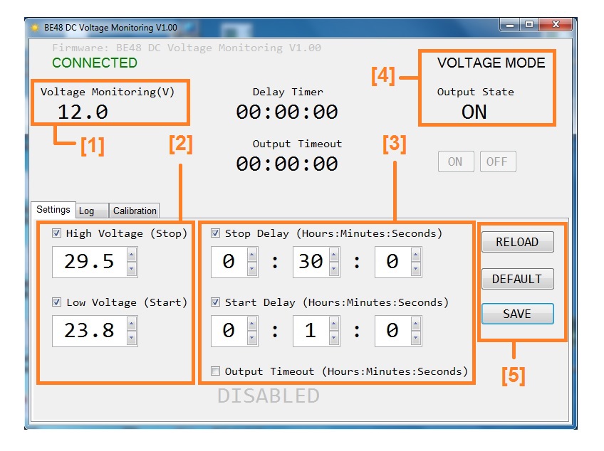
[1] Battery voltage measurement [2] Thresholds settings [3] Timing settings [4] Mode of operation [5] Main buttons
STEP 3 VOLTAGE SETTINGS
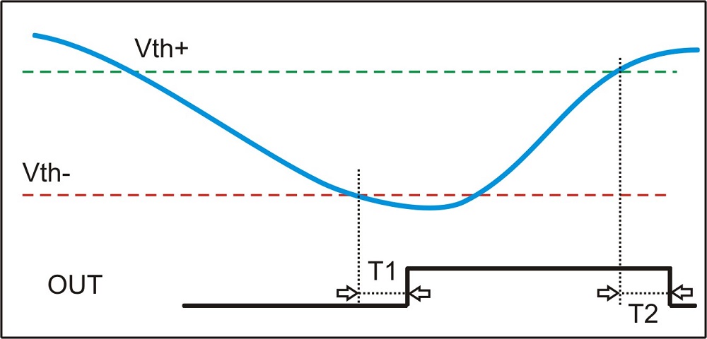
'Low Voltage Start' is the voltage level of the battery that triggers the timer 'T1' (once 'T1' expires, the output relay turns on). 'High Voltage Stop' is the voltage level of the battery that triggers the timer 'T2' (Once 'T2' expires, the output relay turns off).
Set 'Low Voltage Start' and 'High Voltage Stop' according to your needs by using the mouse over the up/down arrows.
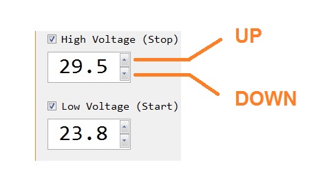
To guarantee stability we recommend that you maintain a minimum difference of at least 2 V between 'Low Voltage Start' and 'High Voltage Stop'. 'High Voltage Stop' must always be set higher than 'Low Voltage Start'.
STEP 4 TIMING SETTINGS
START & STOP delay timers are used to provide flexibility to your application. You can use these timers to avoid false start and stop commands. As a matter of fact, the voltage comparator itself has a fast response and may cause system instability.
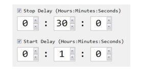
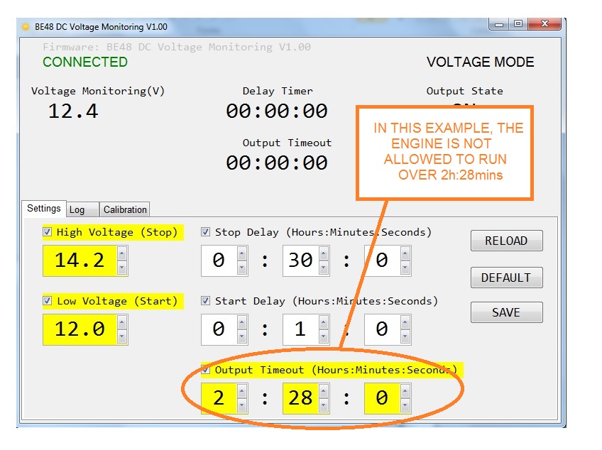
In this example, the output relay turns on after one minute (T1) and turns off after 30 minutes (T2). You can put the timers to zero when Be48 is used in particular applications. The range of the timers spans from one second up to 24 hours. This picture makes it clear.
STEP 5 THE BASIC COMMANDS
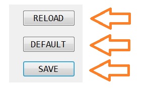
The basic available commands are SAVE (to store a parameter), DEFAULT (to use factory settings), and RELOAD (it cancels a modification and restores the previous setting). If you modify a parameter, a yellow background will warn you. Once stored in the memory the yellow background will disappear
STEP 6 OPTIONAL TIMEOUT SETTING
UNDER OVER VOLTAGE TIME RELAY
This additional timer is extremely important when you want to add security to your system. If there is a failure on the charger, you will never be able to charge the battery or you will risk overcharging it. This timer limits, for example, the run time of the engine. Once the BE48 triggers the alarm, you are required to remove the DC power supply by removing the JA plug for a few seconds. This will reset the alarm.
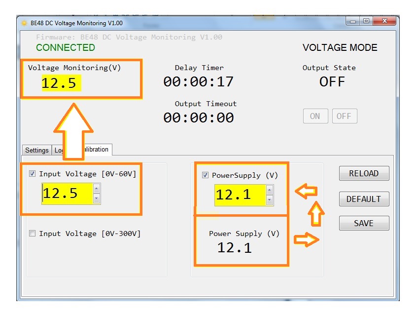
STEP 7 OPTIONAL VOLTAGE CALIBRATION
WARNING!
CAUTION!
PAY ATTENTION TO THE COMMON GROUND LOOP WHEN YOU CALIBRATE FOR A BATTERY OVER 60VDC. YOU MAY DAMAGE YOUR COMPUTER. HIGH DC VOLTAGES MAY BE EXTREMELY DANGEROUS. THE CALIBRATION PROCEDURE MUST BE CARRIED OUT BY QUALIFIED PERSONNEL ONLY. WE RECOMMEND THAT YOU PUT PROTECTION FUSES ON THE BATTERY SIDE
The factory precision of the measurements is about 1%. If you want more precision, we recommend that you carry out the calibration. Use a precise measurement instrument for the battery and you will take note of the measurement. Push the button [Calibration]. Choose the proper range: 60V or 300V according to your measurement. Use up and down to match the measurement and then push the button 'SAVE'. The Be48 will calculate the correction factor. You will get in a few seconds the reading with approximately 'NO ERROR'. A good calibration will allow you a 0,1% accuracy. The calibration is stored in a NON VOLATILE memory.
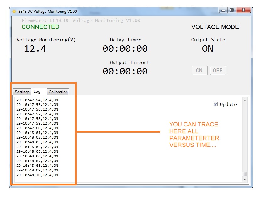
DC VOLTAGE LOGGER
If you want to carry out really accurate testing of the system, the BE48 provides a real-time data logger. By analyzing the TIMESTAMP you can find out if the system works as you expect. To make LOG HISTORY perform accurately you are required to maintain your computer connected to the BE48 monitoring relay. We recommend that you use a fully isolated USB repeater. Using normal cable extenders you can cover distances up to 20 meters without problems.
BE48 LED INDICATORS AND DIP-SWITCH
The DIPSW 1 and 2 are not used in the standard version. The DIP3 is momentarily used to enter the configuration procedure.
The DIP4 activates the comparator output relay. You can use it to make a test. As long as the switch is activated (on) the DL4 will continuously blink.
The DL1 green indicator turns on when the CPU is running. It blinks fast when the DC supply is lower than 8Vdc for at least 5 seconds. In this case, the Be48 turns continuously on the red LED indicator DL5.DC Supply: 5.5/36Vdc, 50/150mA
The DL2 yellow indicator blinks slowly when the battery voltage is lower than the threshold. It blinks fast when the battery voltage is over the threshold. It remains lit when the voltage is within the settings
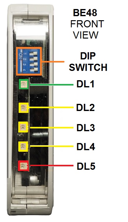
The DL3 yellow indicator is normally off. It blinks when the Be48 activates a timer T1 or T2
The DL4 yellow indicator turns on when the output relay JD1-2 is energized. It turns off when the relay output is off. It blinks fast when the BE48 is in TEST MODE (DIPSW4 is in its ON position).
The DL5 red indicator turns on in case of alarm time-out (it energizes the relay alarm and de-energizes the rlay comparator output)
The DL5 turns on when the DC falls below 8VDC for at least 5 seconds. The alarm auto resets when the voltage rises above 8Vdc.
BE48 SPECIFICATIONS
DC Supply: 5.5/36Vdc, 50/150mA
Aux supply output: 600mA @ DC Supply-0.5V
Protection: 300mA thermal fuse
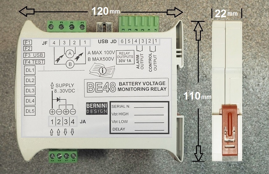
Dimensions:: 110 X 120 X 22 (mm)
DIN RAIL mount
Operating temperature: -25 deg C up to +70 deg C
Humidity range: 5% up to 95%
Weight: 130 grams
Meets ECC 89/336, 89/392, 73/23, 93/68, IEC 68-2-6
Certification: CE
Yellow LED Indicators: 3
Red LED Indicator: 1
Green LED Indicator: 1
DC Relay Outputs: 1A 30VDC.
AC Relay Outputs: 5A 250V AC
Connectors: removable terminal blocks
Battery monitoring Vdc: 5-500Vac
Configuration via USB
Battery monitoring Vdc: 5-400Vdc
Zona Industriale
46035 Ostiglia Italy
0039 335 7077148